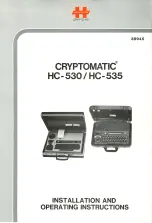
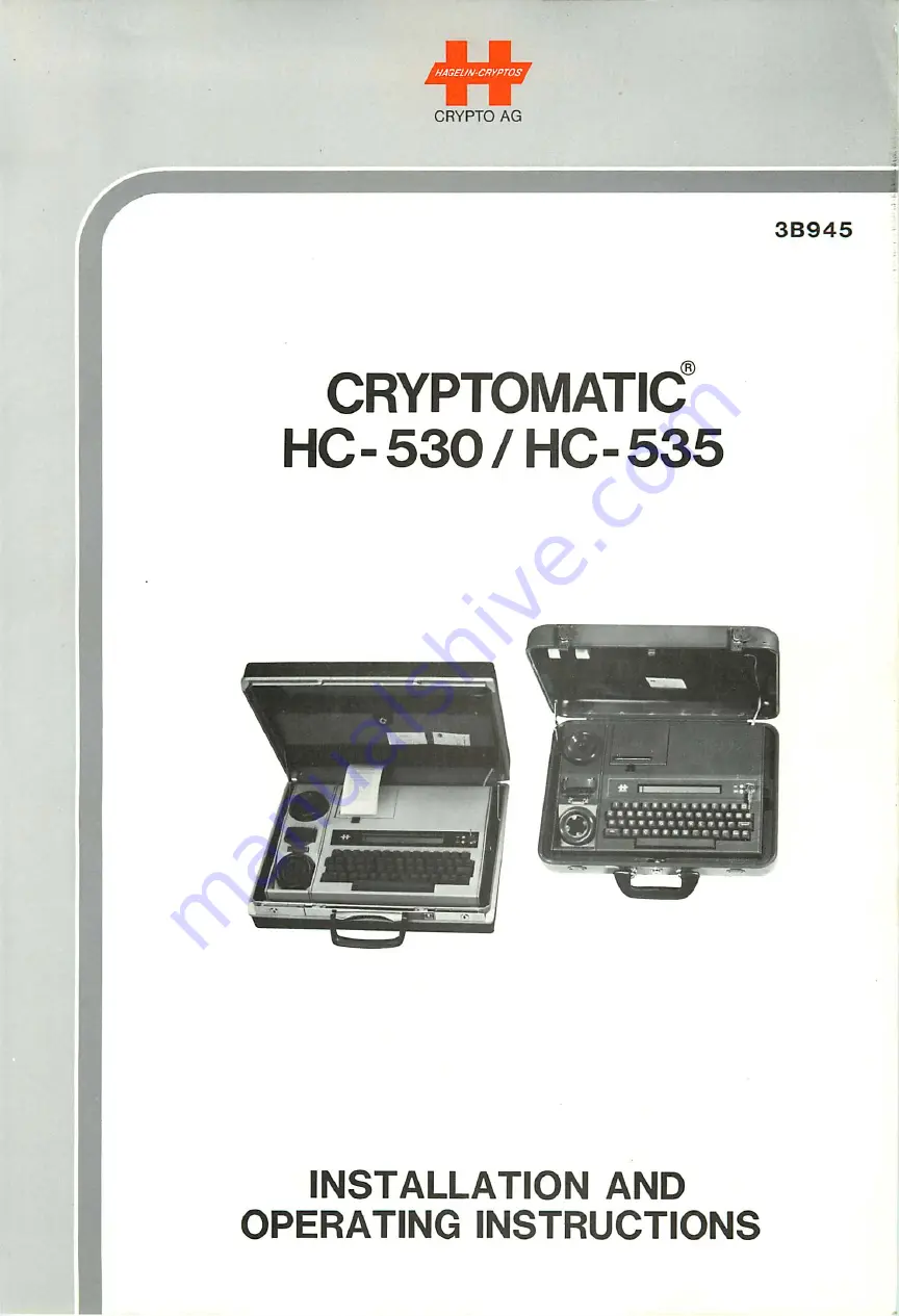
background image

Summary of Contents for CRYPTOMATIC HC-530

Page 1: ...SNOiionaiSNi ONiivaado QNV NOIlVmVlSNI 9eS OH 0C9 OH JDUVIAIOldAUO 9t 6ae 9V OldAHO SOldAUO NmOVH...

Page 2: ......

Page 3: ...ISONOUS CADMIUM NEVER DISPOSE OF WORN OUTACCUMULATORS IN THE GARBAGE NEVER OPEN THEMAND NEVER BURN THEM RATHERALWAYS RETURN THEM TO CRYPTO AG FOR RECYCLING CAUTION BEFORE CONNECTING THE LINE CORD TO Y...

Page 4: ...3 5 COUPLERS 1 2 1 3 1 4 1 4 1 5 1 3 5 1 ACOUSTIC COUPLER 1 3 5 2 GALVANIC COUPLER 1 5 1 5 1 3 6 POWER SUPPLY 1 3 7 ACCESSORIES 1 3 8 OPTIONS 1 6 1 7 1 9 SPECIFICATIONS 2 1 2 1 TECHNICAL DATA HC 530...

Page 5: ...GRAMMING OF VARIABLE PARAMETERS VP 4 3 2 MODIFICATION OF A VALID VP COMBINATION 4 3 3 CLEARING THE VP DATA 4 3 4 TWO VARIABLE PARAMETER COMBINATIONS 4 3 5 STATION IDENTIFICATION ID FOR SELECTIVE CALL...

Page 6: ...2 3 4 5 4 5 RECEIVING WITH ACOUSTIC COUPLER 4 23 4 5 4 6 RECEIVING WITH GALVANIC COUPLER 4 25 4 5 4 6 1 GALVANIC COUPLER AND RADIO O P E R A T I O N 4 2 8 4 5 4 6 1 1 CONNECTIONS FOR RADIO 4 28 4 5 4...

Page 7: ...V I f 6 1 7 1 7 3 0 0 W d 0 1 I 0 3 O T b Z 1 7 1 7 N O I I V R N I I N O O 9 N I t i 3 H d I 0 3 a 1 7 6 1 7 Z 1 7 1 7 3 3 V J t i 3 1 N I 1 V I t t 3 S 3 H 1 V I A 9 N I U 3 H d I 0 3 a 6 1 7 9 1 7...

Page 8: ...OSTIC TEST PROGRAM 6 7 6 4 1 1 GENERAL TEST DETAILS 6 4 1 2 FAULT SIGNALIZATION 6 9 6 14 6 4 2 FUNCTIONS DIAGNOSED BY DIAGNOSTIC TEST PROGRAM 6 15 6 4 3 FUNCTIONS NOT DIAGNOSED BY DIAGNOSTIC TEST PROG...

Page 9: ...he various text input and output possibilities as well as a powerful microprocessor system give the units an exceptional flexibility Operation of the units is simple and logical The units will operate...

Page 10: ...printed circuit PC boards in EURO format Couplers acoustic and galvanic with common modem Power converter PC board for internal voltages AC charger module Accumulator i e rechargeable battery pack The...

Page 11: ...a p o u i 6 u j 4 U U d d a p o u i q n d u i q x a i I O p O l U A 9 D L S B Q g a p o u i p u B i u u i o o j o q L U O W W a p o u i 6 u L U i u i e u 6 o u d u e q a u i B J B d 9 L q e j u B A A...

Page 12: ...d Paper feed can only be carried out when the unit is in monitor mode status M 1 3 4 SERIAL INTERFACE The serial interface serves for serial data input and output as well as for test purposes The asyn...

Page 13: ...ciphered messages over telephone lines The design of the telephone coupler allows coupling to practically all current types of telephone hand sets Transmission takes place synchronously 1 3 5 2 GALVA...

Page 14: ...pply power to the printer the accumulator will thus be discharging somewhat when the printer is in use The accumulator can of course supply power if both operation and printing when the mains supply i...

Page 15: ...30 Tape Punch Reader for producing and reading paper tapes in the 5 bit Baudot code CCITT No 2 at 200 baud PSB 530 DC Charger Module for a supply voltage of from 10 to 30 VDC ATX 530 Teleprinter Inter...

Page 16: ...AG 1 1 PTS 530 ADA 530 ATX 530 Thermo paper HF Link Frequency Teleprinter Rolls Adjustment Indicator Interface 542 101 TPR 530 Tape Punch Reader Station PSB 530 DC Charger Module Figure 1 1 HC 530 535...

Page 17: ...hone Galvanic 546 944A Free End Switchover Interface Also for radio 546 674 SE 20 547 899 PRC 77 Ha ndset 547 925 PRC 77 Wi deband 546 816 SYNCAL H a r r i s etc Back Back Connector 546 945A TEA 530 D...

Page 18: ...er This allows unattended receiving station operation either ciphered or plain Galvanic Coupler Cable and Plug for radio applications Appendix A5 ADA 530 HF Link Frequency Adjustment Indicator for rad...

Page 19: ...2 5 b i t c o d e Data Input Keyboard serial IN acoustic or galvanic coupler Data Output Display printer serial OUT acoustic or galvanic coupler Data Memory C a p a c i t y 2 0 0 0 c h a r a c t e r...

Page 20: ...a t r i x 38 characters status indicator Character resolution 5x7 cursor underline Character dimensions 4 5 x 3 mm approx Serial Interface 25 pole Cannon female connector DB 244 or M24308 2 3 Test sig...

Page 21: ...second Simplex transmission Selectable without return channel Sensitivity Better than 45 dB Modem frequency CCITT V21 channel 2 1850 Hz 1650 Hz Automatic connection control during operation start up...

Page 22: ...hours empty full Fusing 1A standard fuse on power converter PC board Separate 4 8V Ni Cd accumulator on keyboard display PC board for basic key and variable parameter protection AC Charger Module Inpu...

Page 23: ...ccumulator must then be recharged 2 2 SYSTEM SPECIFIC PARAMETERS M T B F 1 5 x 1 0 3 h B 0 9 Test Diagnostic Self test upon switch on Troubleshooting in conjunction with optional diagnostic test softw...

Page 24: ...530 ONLY Test according to MIL STD 810 C Low Temperature Method 502 1 1 Operating temperature 0 C Storage temperature 20 C High Temperature Method 501 1 1 Operating temperature 55 C Storage temperatu...

Page 25: ...Method 501 1 1 Operating temperature 55 C Storage temperature 70 C Humidity Method 507 1 11 55 C 95 Relative Humidity Rain Method 506 1 II Unit in Case 2 hours Vibration Method 514 2 X Unit in Case 7...

Page 26: ...RYPTOAG 2 6 MECHANICAL DATA HC 530 535 Dimensions without case 402 L x 100 H x 294 D 2 1 with case 465 L x 125 H x 365 D Weight w i t h o u t c a s e 6 5 k g w i t h c a s e 9 4 k g ALL SPECIFICATIONS...

Page 27: ...se is set to 000 and the case may be opened by resetting to this combination The combination may then be changed as desired see Samsonite instruc tions 3 2 PACKING AND STORAGE The original packing mat...

Page 28: ...35 terminal can then be connected to the mains supply and switched on by means of the mechanical security key Immedi ately after switch on some characters appear on the display This indicates that an...

Page 29: ...T 17 pn jaq uj Jd Japun uoq q nqqsnd paaj JadBd j o uoj q Boo i SMoqs mojjv Z 9 n6j j qoq LMS Joq oaLas a6Bq LOA 10 uoj q BOO SMoqs mojjv I 3Jn6j j 9V OldAHO Sl76a SOJdAHDN 73DrH...

Page 30: ......

Page 31: ...as follows CONTROLKEY RKEY CTRL R 4 NEW LINE KEY Command inputs must be terminated by pressing new line key i e The commands CTRL A CTRL R and CTRL X are exceptions and do not require terminating with...

Page 32: ...IN MEMORY CTRL P CIPHERING CTRL I INPUT TEXT FOR CIPHERING CTRLR CTRL C F O R CTRLCD CTRLCP CTRLCS Display Printer Serial CTRL CT EED Coupler ERASE TEXT CTRL X Y STATUS INDICATOR MUST NOT BE V OR B DE...

Page 33: ...IfldinO 0Nld3Hdl030 3fllVA dA 01 ONIOdOOOV 30IA30 lndlHO 300W 0Nld3Hdl030 30Vdd31NI Vld3S d31dfK 0 d31Nldd AVldSIO 30IA30 indinO ONId3HdlO 3fllVA dA 01 ONIOdOOOV 30IA30 lndlflO 300W ONId3HdlO 030NVH0...

Page 34: ...MODE The monitor mode left window of display shows M is the start ing point for all operating modes A new operating mode can only be selected when the unit is in this mode When the HC 530 535 is swit...

Page 35: ...UOLU oq sapoiu Le uiOvij uunq oj A blu noA p9J9q U9 oq q s u i q snui Bq Bp dA 9M1 9 oqM OAoqB A Loq BLpeLULUL poquosop oporn dn q iBq s dA 9UA uoLq dooxo oqq qq Lfl S t7 pub t7 f suol dos oos q nq OA...

Page 36: ......

Page 37: ...ibuuo gpoo o I LPH S 9dA I A U B L o d o I L B u a s 9 d A 33Vdti31NI V I d 3 S t i O d I i n d i n o e u i a s o p 9 9 d s t d A 6 q ndu L 6 Mas o paads dA i 90LA9p q ndq no pawUa La id ZdA I a npao...

Page 38: ...z o r m 2 U l 03 O O m X H m X H 0 Z O O l C 5 3I 1 m i O Z z O en O 01 O T J T l m O ro o o h D 33 r s s 2 0 CO O l e n C O C O r f t O i 0 0 4 k n O H A 3 r Oi en 0 en 0 cn o O i 0 33 r 0 ro 0 0 ro...

Page 39: ...modifications next section below One possible example of VP programming is shown in Table 4 4 Note Keying in a VP value not filled in on Table 4 3 will result in rejection of the entire VP with retur...

Page 40: ...H C O T J m m o c n o 03 O C O 3 m n j j C O r m o 33 c TJ C H C O TJ m m o cn 03 D TJ O r 33 H o 33 C D CO m 33 O O o m c o o TJ 03 X H Z m HOB 7 s O m c o j m m z 2 33 H O o m z m 33 m o o m co 33 m...

Page 41: ...be altered as detailed in the previous section How ever it is possible to clear the VP memory as follows 1 Enter CTRL R 2 Set the machine to VP mode by entering CTRL V j 3 Enter CTRL X whereupon the q...

Page 42: ...2 2 1 1 2 X 2 2 X For use with ATX 530 Teleprinter Interface Section 1 3 7 and teleprinter 50 Baud message key input via keyboard cipher text format in 10 letter groups V P 2 1 9 9 1 6 1 1 1 2 2 For u...

Page 43: ...D The input requires five numbers in the range 0 to 9 The five numbers are given in on the keyboard and then programmed into the HC 530 535 with the key The ID is then stored in non vola tile Ni Cd pr...

Page 44: ...turn on or following reassembly after opening the housing with the main switch to OFF the HC 530 535 terminal will display BK MISSING ENTER CMD This requires entry of basic keys See following sections...

Page 45: ...lay Possibility 2 No Master Key Defined If one or more basic keys have already been entered and no key has been defined to be the master key the display format will be e g BI j_ GV MV LO KI The j_ _ s...

Page 46: ...alphabet may be used here as de sired Then press the space bar Now enter the 20 letters of the basic key in groups of five letters Press the space bar between groups Make corrections as necessary usi...

Page 47: ...ENTER CMD or NEW MASTER BI AA EXEC If BK MISSING ENTER CMD is displayed then no basic keys have been entered In this case see the previous section If the basic keys have been entered the display will...

Page 48: ...ready entered keys do the following Enter CTRL R CTRL B Press M Press the space bar until NEW MASTER BI EXEC appears on the display EXEC means Execute Press Y for Yes 4 4 1 1 4 C FOR CANCELLING BASIC...

Page 49: ...key The unit will return to monitor mode when all bigrams have been displayed 4 4 2 BASIC KEY EMERGENCY CLEAR You can cancel all basic keys at one time Emergency Clear by entering CTRL R CTRL B CTRLX...

Page 50: ...her 38 characters can be entered After completion of text input monitor mode must be re selected by entering CTRL R When the input mode is exited the text is compressed Non essential characters such a...

Page 51: ...W can be used instead of the DEL and WORD keys respectively 4 5 3 TEXT INPUT MODE WITH SERIAL INTERFACE This mode is in principal identical to the keyboard input mode described in the previous sectio...

Page 52: ...reception via coupler the information received will be automatically output in ciphered or deciphered form depends on the programming of the variable parameter VP10 Coupler reception is signalled on t...

Page 53: ...rage of text into text memory Local processes not interrupted No backup storage of text in text memory Backup storage of information in text memory if space available there Local processes not interru...

Page 54: ...ust be restarted 4 5 4 3 MANUAL INTERRUPTION OF THE COUPLER AUTOMATIC OUTPUT PROCESS Manual interruption of the automatic output process is rarely necessary but can be done as follows if ever required...

Page 55: ...uring the automatic output process if desired as follows Enter CTRL X The display will then be CLEAR RECEIVING MEMORY EXEC Entering Y will then clear the entire receiving memory NOTE The text memory w...

Page 56: ...RYPTO AG 4 24 Figure 4 1 Receiving Ciphered or Plain Text Via Telephone Transmission in plain is possible by using an extended header section 4 5 TFG 530 or Radio Figure 4 2 Receiving Ciphered Text vi...

Page 57: ...s its own modem Switchover from acoustic to galvanic operation occurs automa tically as soon as the galvanic coupler is connected to an audio interface such as e g the TFG 530 Telephone Galvanic Switc...

Page 58: ...nterface Connections Optional To Puncher Teleprinter or Printer Serial Interface Using Acoustic Coupler i 1 i i c n E o o 3 C O 10 6 z HC 530 535 Application TFG 530 Used for One Subscriber Acoustic C...

Page 59: ...peH enqoyy e ui uo eo ddv 9S9 0C9 OH 1 1 o o 1 1 j 1 n xa xi e s e g dfl IIBO dnojo hbq aAijoaias uoijBonddv jseopeojg ui jajdnoo ojubaibq uoueoi ddv geg oeg OH 1 1 o a O xu Se9 0C9 0H o o l o 1 9e9 0...

Page 60: ...modulated AM or single side band SSB radios having stable phase locked loop PLL circuitry can also be used with the galvanic coupler 4 5 4 6 1 1 CONNECTIONS FOR RADIO An X mode plug can be used to ad...

Page 61: ...ap jo iooqpuPH Leo LUip9i S S 0 S OH 9 Ml pup 6ulmollo g f 9unfi ij oq a aj p noqs uppLuqoaq aqi ainpoiu ja d noo aqi o UPd sl god s Lqi Cdi pup Zdl stuuod S9 VI 9 S17S 83d P oq iLnojp pa uwd uo pajn...

Page 62: ...HAGEUN CRYPTOS 3B945 CRYPTO AG 4 30 1 C O I Q_ CM LJ m C N M l rr I T o u O csi 5 n n Figure 4 5 Galvanic Coupler Audio Switch PC Board...

Page 63: ...on the message will be output automatic output process of Section 4 5 4 2 as programmed by the variable parameters The receiving memory is then automatically erased Possibly acknowledge receipt of mes...

Page 64: ...which is to receive messages and its associated radio plug the cable from the ADA 530 into the galvanic coupler socket of the HC 530 535 Plug the cable from the radio into the ADA 530 The transmittin...

Page 65: ...can deliver The additional current is provided by the accumu lator The accumulator is therefore used from time to time even if the unit is connected to an external power source this however is favoura...

Page 66: ...t is available to copy the memory contents to other units such as magnetic cassette recorders or paper tape puncher units 4 7 1 SELECTION OF SERIAL OUTPUT MODE The unit must be in monitor mode and CTR...

Page 67: ...ll be via the preferred output device programmed in the VP mode VP2 In the VP mode the following parameters for ciphering mode can be programmed Sec tion 4 3 VP7 Message key automatic or manual VP8 BK...

Page 68: ...d BI should now be entered followed by If the HC 530 535 has been programmed for manual i e local messaqe key MK entry VP7 2 ENTER MK will be displayed The correct MK must then be entered 5 letters sp...

Page 69: ...nd printed The HC 530 535 returns automatically to monitor mode at the end of the process Should the printing paper run out the process can be stopped with CTRL R and the process repeated after new th...

Page 70: ...is connected Section 4 3 Ciphering via the serial interface is selected by entering CTRL CS or CTRL C if the serial output is the pre ferred output If the HC 530 535 has been programmed for manual i...

Page 71: ...hone handsets on the rubber pads of their units Figure 4 1 The earpieces should be on the rear pads and the handsets centered Each handset should then be secured with its rubber strap The transmitting...

Page 72: ...ND OF PART PRESS C KEY WHEN READY In this situation the telephone handset should be removed from the HC 530 535 for the purpose of communicating with the operator of the receiving station When the rec...

Page 73: ...y the transmitting terminal can specify which of several individ ual or groups of terminals is to receive a message For the HC 530 535 selective call functions with the galvanic or acoustic coupler Th...

Page 74: ...o n w i t h l a b e l i n g o f the transmitter terminal given in the deciphered text at the receiving termi nal NOTE The transmitting terminal of a coupler message will always be indicated on the dis...

Page 75: ...noj6 ipqi jo s puuiuai aqi LLe 3 luas aQ LL LM aBpssaui aqi uaqi inv oj v jana aqi qij M paop daj sl PULUuai 6UL11J LUSUPJ1 p ip paioa as ssajppp up jo jaquinu aqi ji a pup g v sdnoj6 01 6uo _aq p noM...

Page 76: ...nuation Selection of the deciphering output device can be by default in the same manner as described in Section 4 8 for the cipher ing mode The text to be deciphered must be entered via the keyboard i...

Page 77: ...with the text to be deci phered and more than one BK is stored then ENTER BI will appear on the display The desired two letter bigram should then be entered via the keyboard and terminated with If the...

Page 78: ...pleted IN PROCESS is displayed Dependent on the length of text 15 seconds may pass because the entire page must be processed before printing starts At the end of the process the unit returns to monito...

Page 79: ...CESS is dis played After completion of processing the unit returns auto matically to the monitor mode Should the HC 530 535 remain blocked in this mode check to ensure that the serial output speed VP4...

Page 80: ...hed and the message noted clear the memory with CTRL XY The HC 530 535 should not be switched off in order to avoid loss of the key generator position f Continue text input from next character after t...

Page 81: ...f mode selection and exit from mode are not executed at con trol level CTRL key must not be pressed See Table 4 5 and the following information The following characters are accepted in editor mode and...

Page 82: ...CURSOR TO THE LEFT WITHIN DISPLAY D DEL L LOCATE MODE DELETE CHARACTER AT CURSOR POSITION I INSERT MODE C CHANGE MODE L T E X T L O C A T E SEE EXAMPLES BELOW HAGEUN CRYPTOS CRYPTO AG tCLOSING DELIMIT...

Page 83: ...ht normally To use editor mode a message must have been stored in the memory otherwise MEMORY EMPTY is displayed For initial selection of this mode the unit must be in monitor mode enter CTRL R and th...

Page 84: ...he end of the stored text The cursor will be located at the end right side of the text displayed TEXTSEARCH Text search can be carried out in editor mode simply by reading the text as detailed in the...

Page 85: ...ion of the D or DEL key in editor mode the character at the cursor is deleted and the text is closed up this is only valid in the editor mode If the entire text is deleted the unit will return to moni...

Page 86: ...der the first character which is to be changed b Enter C whereupon the status indicator changes to EC c Enter the begin delimiter e g d Enter the new text it will be displayed e Enter the end delimite...

Page 87: ...of a microswitch arrow figure 4 7 This will cause the microprocessor to clear the basic key and station ID but only if the lockable ON OFF main switch top right figure 3 1 is set to OFF If set to ON...

Page 88: ...1 3 uaAOO doi uapun mouuv qoq LMsouoi w i j 9un6Lj mouu qo BQ esea 8y 9 t 9un6ij 99 17 OV OldAHO 5t76ae SOJdAHONUJOtW...

Page 89: ...text is produced unprocessed check that the correct number of advance sequences CTRL A or have been entered Either all or none of the advance sequences must be entered 5 2 POOR PRINTING QUALITY If the...

Page 90: ...conds and then back to ON If despite charging the display flashes after the unit has been switched on the charger module should be checked voltage selection fuses Should the display not appear despite...

Page 91: ...by pushing the release button in the direction shown in Figure 6 1 b Remove the empty paper roll Figure 6 1 Push Printer Lid Release in the Direction of the Arrow to Free Printer Lid c Load new therm...

Page 92: ...ed g wnfiLj 17 9 ajn6i j jbaod aqq ul pap LAOjd q O s aqq q6nojqq spaaj jaded aqq q eqq ajnsua pup jbaod jaq uj jd aqq asoto j 9 ajn6j j ul UMoqs se sjeadde jaded aqq L 4un Z 9 9Jn6j j ul UMoqs uoqq n...

Page 93: ...ed soon after printing DO NOT STORE IN HOT HUMID ENVIRONMENTS Unprinted Jujo Thermal retains its printability for more than 5 years when stored in the dark at an ambient temper ature of less than 30 C...

Page 94: ...ree After long periods of either storage or use without a mains supply however it may be necessary to re charge the accumulator before the unit is operational see Section 1 3 6 Expected accumulator li...

Page 95: ...s is true even if the unit is now accidently turned off Just be sure the lockable main switch is turned ON before installing the accumu lator if the basic key is to be saved NOTE We do not recommend o...

Page 96: ...HAGEUN CRYPTOS 3B945 CRYPTOAG 6 6 5 5 Wr o J v V T1m J k V Figure 6 5 Accumulator Pack Can be Slid Out After Removing Side Plate...

Page 97: ...ns if you enter P a printer test will be performed If the printer passes the test the printout will be similar to that shown at the top of figure 6 6 but longer If the printer is defective a protocol...

Page 98: ...W i l l H i l l HBII H i l l H i l l N i l H i l l H i l l K i t s HEil H i l l H i l l a i l H 3 n n T i i i fi n a Si ei E i i l l E l l l m i ens m i in n i l s i s I I I s i l l EIIS I I I I i n s...

Page 99: ...N T 9 d qvi ul uaAi 6 aje oq a paiujojjad sq saq 6uLuiLq A PLdsi p au i q j un aqq xxo 6uLipq LMS A q paq dnjjaq ui aq a luo ueo q saq SLijq 6ui uunj aouo aAoqe waq L xsjl i aas appiu scm A jq ua ou x...

Page 100: ...Part of Diagnostic Test TESTRUNS 20 sec Lower address region of RAM is tested written and then read POWEROFF NOTALLOWED 20 sec Basic key BK and variable parameter VP part of RAM is tested data saved a...

Page 101: ...nter points acti vated If good then printout per top figure 6 6 All symbols walk across display one after the other 75 sec Display test Test is no longer auto matic in the sense that the symbols shoul...

Page 102: ...tone via the acoustic coupler dis play the fault and then continue on When the output protocol gives a diagnosed failure associated directly with an IC number the failure is not necessarily confined t...

Page 103: ...ground noise and room acoustics In order that the test program can be started the following functions of the HC 530 535 must be operating properly 5V supply Clock generator Power on detector Microproc...

Page 104: ...message key random number generator g Printer The printed protocol has numbered rows characters with all printer thermal points acti vated and the currently active thermo printer temperature compensa...

Page 105: ...o c k fl a s h i n g d On the memory board The power consumption of the non volatile memory e On the printer control Paper advance mechanical f On the coupler The bit control e g transmitter crystal...

Page 106: ...9 C 9 0 H 0 C 9 0 H 9 t 6 S S i V xjpuaddv S 9 S B 0 9V OldAdO S01dA80 Nn30VH 9C9 OH uo SJ8A Aje l IAI JOi 9SBQ 0S9 0H uoisjeA l A 0 Jox asBQ...

Page 107: ...802 MICROPROCESSOR MEMORY PROG DATA COUPLER THERMO PRINTER PRINTER OFF on DC DC CONVERTER 1 IACCUMULATOR r COUPLER 1 MODEM 3 5 GAL VANIC ACOUSTIC CHARGER MODULE 220 110 VAC OPTION 10 30 VDC HAGEUN CRY...

Page 108: ...Interrupt NMI TTL Test Start 1 0 Tel Out Busy TTL Te s t P o s s i b l y E x t M o d e m 1 1 Clock Tel TTL Test 1 2 Input Ready TTL 1 3 Serial Data OUT TTL T P R 5 3 0 1 4 Serial Data IN TTL _ J 1 5 S...

Page 109: ...r Operating Mode ON if at OV 8 O V Ground for TFG 530 or Radio 9 TRR Transmit Radio Audio Signal Level adjustable from 60 to 10 dbm TRR TRGN circuit closed with relay contact in TRR line but only duri...

Page 110: ...puv iq o je dnoQ osubajbo 9V OldAdO SOldAHD NmOVH l 2W p 8 MS i q u 6 M piu 06 uaiA P H Q n u p i i 2Z XI X19 N93d N D d i U t i l AO VJi t r j I 1 1 1 i d 1 j 5 l 1 p j I l 1 i q eT J m a 1 a A LI 1...

Reviews: