6 - 2
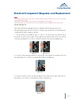
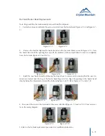
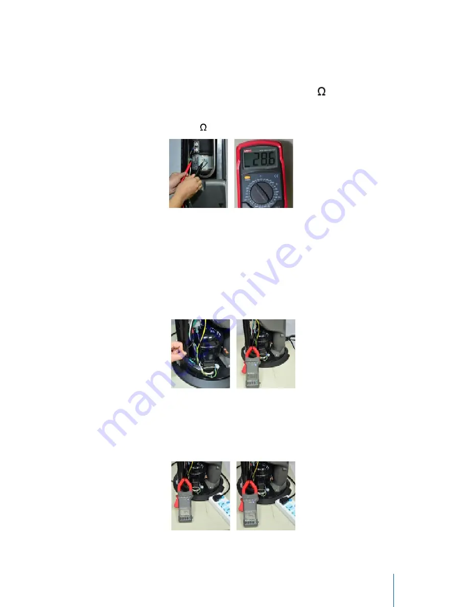
The heater band can be tested for resistance using a multi-meter set to 200 ¸
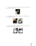
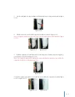
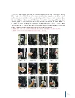
4. Touch the two terminals on heater band with the sensor probes (Figure 6-1-5). The proper re-
sistance is within a range of 28 to 32.2 ¸ (Figure 6-1-6).
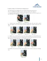
An amperage draw test can be done on the compressor and the heater using a clamp meter.
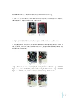
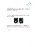
5. With the hot tank switched off and the unit unplugged. Locate the main lead wire coming in
from the power cord to the cold thermostat (Figure 6-1-7) position clamp meter around this wire
and switch on (Figure 6-1-8).
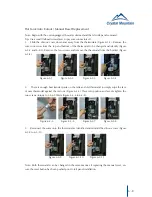
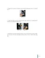
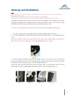
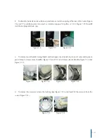
6.Plug in the dispenser. After an initial spike the reading should be within the range of 1.1-1.6A
(Figure 6-1-9). Turn on the hot tank switch; and the reading should increase to a range of 4.3-4.8A
(Figure 6-1-10). Caution: do not leave hot tank switch on for longer than 5 seconds.
Figure 6-1-5 Figure 6-1-6
Figure 6-1-9 Figure 6-1-10
Figure 6-1-7 Figure 6-1-8

