4
INSTALLATION
SYSTEM OPERATION
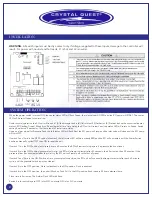
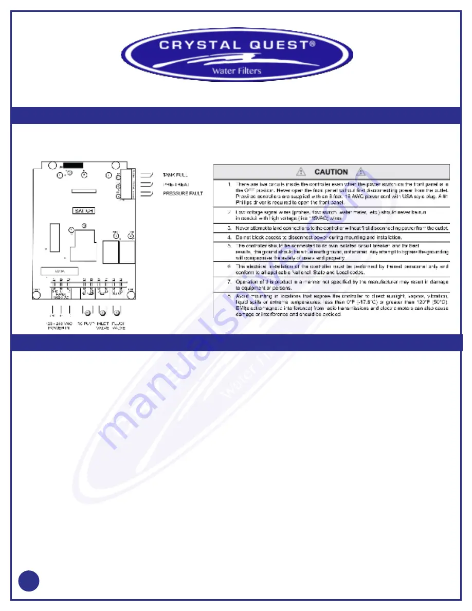
When the power switch is turned ON, the center status LED will flash Green, the inlet valve will OPEN and the RO pump will START. The center
LED will be solid Green for normal run.
Under normal operation the RO unit will run until: (A) the storage tank is full (left status LED Amber) or (B) Pretreat lockout has occurred (center
status LED Flashing Green). When A or B has cleared, after a time delay, the RO unit will restart, and the status LED will return to Green. Switch
setting 3 selects a 2 second or 15 minute tank full restart time delay.
Upon an alarm signal for Pressure Fault, the left status LED will flash Red, the RO pump will stop and the inlet valve will close and the RO pump
will turn OFF.
If switch 1 and 2 are in the OFF Position (disabled), the left status LED will be a steady RED and the RO will not restart until the Power Switch
has been manually cycled OFF then ON to reset the unit.
If switch 1 is in the ON Position (auto reset), every 60 minutes the RO will start and stop again if a pressure fault continues.
If switch 2 is in the ON Position (pressure fault retry), the RO will attempt to restart after 30 seconds, then 5 minutes, then 30 minutes. If the
pressure alarm has not cleared after the third try, the RO unit will remain off until manually reset.
If switch 1 and 2 are in the ON Position, after a pressure fault condition, the RO unit will continually attempt to restart after each 60 minute
cycle, until the pressure switch input has cleared.
If switch 5 is in the OFF position, Flush is disabled; in the ON position, Flush is enabled.
If switch 6 is in the OFF position, the unit will flush on Tank Full. In the ON position, flush is every 24 hours elapsed time.
Flush time is 5 minutes. The Amber Flush LED with flash.
Switch 4 is for switch inputs. OFF is for N.O. contacts. ON is for N.C. contacts
WARNING:
All switch inputs must be dry contact only. If voltage is applied to these inputs, damage to the controller will
result. For power with neutral and hot leads, L1 is hot and L2 is neutral.


