background image

Crystal Vision 


Statesman


27/10/2006 

8


GPI 36 User Manual R3.0 

Input testing 

A GPI line configured as an input, which is normally connected to a semiconductor 
output driver, may be tested to determine if the input is open circuit (disconnected). 

Note: 

Input testing will not work with a non-semiconductor input such as a simple hardware 
switch. 


Setting the GPI active level 

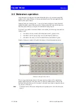
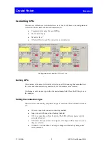
There is a two-button control that sets the active level of the GPI connection. When the 
connection is configured as an output in salvo mode the button will indicate a pending 
condition with a change in colour to dull red.  

Using Salvos 

A Salvo consists of a number of 'primed' output state changes that are all changed when 
the Salvo button is pressed. To set one or more GPI lines using a Salvo proceed as 
follows: 


Prime one or more GPI lines for Salvo operation by checking 'OP Salvo' 


Select the required output state – the button will change to dark red 


Press the Salvo button – the dark red selections change to bright red and the 
outputs change state 

Status indicators 

The ‘OP Error’ LED will illuminate red if the connection is set as an output and the 
setting conflicts with the actual state - the connection is low when set high, or high when 
set low. Otherwise it will be grey.  

The ‘IP Active’ LED will illuminate yellow if the connection is set as an input and the 
actual state matches the active state set. Otherwise it will be grey. 

The ‘No connection’ LED will illuminate red if connection checking is enabled and the 
check indicates an open circuit. Otherwise it will be grey. 

Note: 

Input testing will not work with a non-semiconductor input such as a simple hardware 
switch. 


Summary of Contents for GPI36

Page 1: ...Vision Ltd Lion Technology Park Station Road East Whittlesford Cambridge CB22 4WL England E mail sales crystalvision tv Website www crystalvision tv Tel 44 0 1223 497049 Fax 44 0 1223 497059 GPI36 GP...

Page 2: ...Installing Statesman 5 2 2 Statesman operation 6 Controlling GPIs 7 System monitoring 9 Hardware installation 10 2 3 Rear modules and signal I O 10 3 Trouble shooting 13 Card edge monitoring 13 Basic...

Page 3: ...lectable as alarm warning triggers Input is inactive Connection test detects open circuit on input Output error The GPI36 is a 100mm x 266mm module which fits in the all standard frames and can be int...

Page 4: ...put or an output Input checking function Designed to be used with Statesman Set multiple GPIs using salvos Output current limiting Input protection may be used with input voltages up to 30 Volts May b...

Page 5: ...i directional GPI line configured as an I P Note A low is detected at voltages below 0 8V and a high is detected at voltages above 2 4V Voltages between 0 8V and 2 4V may produce either a high or low...

Page 6: ...the firmware must be V1 04 or above An optional RS422 to RS232 converter if the PC has no RS422 ports Installing Statesman Refer to the readme and or help file on the CD before proceeding To view all...

Page 7: ...quickly the following colour and size coding is used A module is shown present by full colour and absent by greyed colour A module is shown open by large icon size and closed by small icon A module is...

Page 8: ...g Statesman that view this card and when alarms are generated by GPI36 modules in the network To change or edit a name type within the desired name field Press the F11 key to save the changes Setting...

Page 9: ...To set one or more GPI lines using a Salvo proceed as follows Prime one or more GPI lines for Salvo operation by checking OP Salvo Select the required output state the button will change to dark red...

Page 10: ...ch GPI line Output error status for each GPI line Connection status for each GPI line configured as an input with the connection test enabled GPI and error settings The Monitor tab allows all the LEDs...

Page 11: ...ouse up to 12 single height modules and dual power supplies The FR1AV and Indigo 1U frame will house 6 single height modules and a single power supply The DTBAV and Indigo 1U high Desk Top Box has bui...

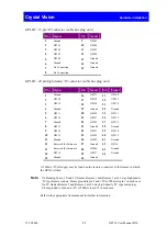
Page 12: ...GPI 32 7 Ground 22 GPI 22 37 GPI 33 8 GPI 13 23 Ground 38 Ground 9 GPI 14 24 GPI 23 39 GPI 34 10 GPI 15 25 GPI 24 40 GPI 35 11 Ground 26 GPI 25 41 Ground 12 Reserved for future use 27 Ground 42 GPI36...

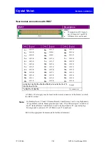
Page 13: ...8a GPI 21 19a GPI 33 12a GPI 10 18c GPI 22 21c GPI 34 15a GPI 11 24c GPI 23 21a GPI 35 19c GPI 12 25c GPI 24 27c GPI 36 6a 8a 11a 14a 17a 20a 23a 26a 29a 31a 3c 6c 8c 11c 14c 17c 20c 23c 26c 29c 31c G...

Page 14: ...control to 0 1 2 or 3 and the Units control to the required position from 0 to 9 For example to select GPI line 17 turn the Tens control so that the arrow lines up with 1 and the Units control so that...

Page 15: ...or open drain output even when the output is inactive not pulling down to ground If IP Conn is selected the input is periodically connected to a negative voltage and sensed whether it pulls below 1V...

Page 16: ...e Press CAL to Exit will be displayed and the CAL LED will light To continue with control panel operation or configuration press the CAL key once A second press of the CAL key will return to Statesman...

Page 17: ...r to internal 5V Typical impedance 10K Level discrimination A low is detected at voltages below 0 8V and a high is detected at voltages above 2 4V Voltages between 0 8V and 2 4V may produce either a h...

Page 18: ...hout active control panel for up to 6 modules Indigo DT 1U Desk top box without active control panel for up to 2 modules Indigo 2A 2U frame with active control panel for up to 12 modules Indigo 1A 1U...

Reviews: