Crystal Vision
Installation
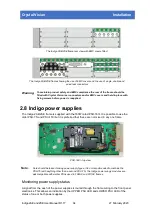
PSU Configuration
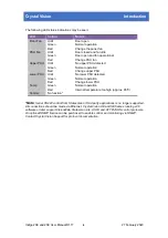
If a power supply is not fitted in either the upper or lower slots, the position of configuration switch
4 on the top right of the front panel PCB must be set down. If both power supplies are fitted,
switch 4 is set up. If the switch is set down and there are two power supplies fitted, the LOWER
PSU LED will flash from GREEN to OFF every two to three seconds to warn that the switch is set
incorrectly.
Address Range
The slot address range switch was used when two frames were paired together to make one
large frame with 24 slots. As this practice is no longer used, switch 5 should be left in the up
position.
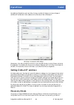
Default IP address
Switch 6 in the down position sets the active front panel into recovery mode with the default IP
address of 10.0.0.201. Recovery mode enables frame firmware updates and also forces the
frame to accept network communications at address 10.0.0.201. Should the frame’s IP address
be unknown, then forcing to the default address will allow access by a web browser whereby the
network settings may be changed.
for more information on establishing an Ethernet connection with a frame
.
Reset switch
Press this switch to reset the CPU following a software upgrade or when resetting the IP
address to its default value.
2.6 Connector pin out
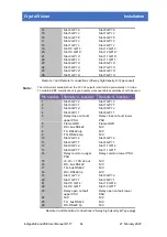
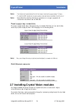
Remote Control / GPI Connections
Each frame slot has six connections that are brought out to one or more of the four high density
D-Type connectors on the rear of the frame labelled Remote 1 to 4. These connections are
referred to as lines 'a' to 'f'. The functions assigned to them are dependent on the module
inserted in each slot, but a typical use is as a GPI line. Refer to the documentation supplied with
each Crystal Vision module to determine the actual functions assigned.
Pin number
Remote 1 - function
Remote 3 - function
1
+5.3V +/- 10% dc out
+5.3V +/- 10% dc out
2
Frame GND
Frame GND
3
Slot 9 GPI ‘a’
Slot 11 GPI ‘a’
4
Slot 6 GPI ‘a’
Slot 8 GPI ‘a’
5
Slot 5 GPI ‘a’
Slot 7 GPI ‘a’
6
Slot 5 GPI ‘b’
Slot 7 GPI ‘b’
7
Slot 2 GPI ‘a’
Slot 4 GPI ‘a’
8
Slot 1 GPI ‘a’
Slot 3 GPI ‘a’
9
Slot 1 GPI ‘b’
Slot 3 GPI ‘b’
10
Slot 10 GPI ‘a’
Slot 12 GPI ‘a’
11
Slot 10 GPI ‘b’
Slot 12 GPI ‘b’
12
Slot 9 GPI ‘b’
Slot 11 GPI ‘b’
13
Slot 6 GPI ‘c’
Slot 8 GPI ‘c’
Indigo 2AE and 2SE User Manual R1.17
13
27 February 2020


