Crystal Vision
Installation
Statesman RS422 term/unterm switch
To terminate the RS422 link, move the switch to the left. To unterminate it, move it to the
right.
RJ45 Ethernet connector
Pin number Function
1
TD+
2
TD-
3
RD+
4 and 5
Not used – 75 ohm resistor to GND in frame
6
RD-
7 and 8
Not used – 75 ohm resistor to GND in frame
2.4 Front panel settings
The Indigo 4 CoolFlow front panel has two control PCBs, one in the upper position to
control the Upper section of the frame (lower slot numbers) and the second in the lower
position to control the lower section of the frame (higher slot numbers) See section 2.7 for
an explanation of the slot numbers.
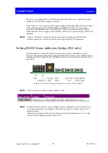
On the upper edge of the front panel PCBs, the config switches and status LEDs can be
found.
PCB top-edge switches and LEDs
Note:
There are two versions of front panel PCB used in the Indigo 4 CoolFlow, these being a
full build and part build. The PCB in the upper position will always be the part build
type. The lower position PCB type fitted will depend on the frame version. The Indigo 4
CoolFlow (passive frame) has a part build PCB in the lower position whereas the Indigo
4SE CoolFlow (active frame) will have the full build PCB.
Indigo 4 CoolFlow User Manual R1.7
14
03/12/2012


