background image

Crystal Vision 

Hardware Installation


M-VIVID User Manual R1.3 

9


18 August 2022 

3 Hardware Installation 

The potentiometers on the card are factory set and should not be adjusted. There are no 

user-selectable links.  

The app based MARBLE-V1 cards are intended for use only in the Crystal Vision ‘Vision’ 

frame range and not in older style frames such as ‘Indigo’. 

Insert the card by pushing the white handle on the card edge, being careful to ensure the card 

is inside the guide rails. Remove it by pulling the metal hook. Do not force the card if 

resistance is met as the card may not be correctly aligned with the rear connectors.  

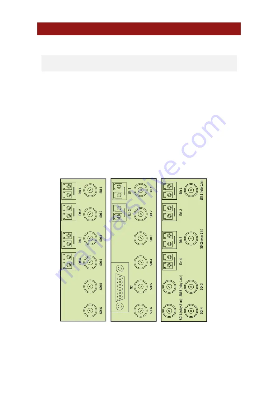
Ensure that the Vision frame has the correct rear module fitted. Only the VR04, VR06 and 

VR07 rear modules offer the correct input/output functionality for the M-VIVID app.  

The cards and rear modules can be inserted and removed without powering down the frame.  

3.1 Rear module signal IO 


VR04 

VR06 

VR07 

Summary of Contents for M-VIVID800

Page 1: ...M VIVID IP SDI video delays Crystal Vision Ltd Lion Technology Park Station Road East Whittlesford Cambridge CB22 4WL England Tel 44 0 1223 497049 sales crystalvision tv www crystalvision tv...

Page 2: ...he Ethernet Interfaces 11 4 2 Enabling Inputs Outputs 13 4 3 Select I O Protocol 14 4 4 Receiving an IP Flow 15 4 5 Transmitting an IP Flow 16 5 Status 18 5 1 Input Video status 18 Video Status 18 5 2...

Page 3: ...ons 29 9 1 Input Format and On Loss of Input 29 9 2 Internal Test Patterns 30 9 3 Audio mute 30 10 Unicast Flow Configuration 31 11 Basic Trouble Shooting 33 11 1 No input or output signals present 33...

Page 4: ...R1 3 3 18 August 2022 Revision 3 User interface screen shots updated to align with V2 3 MARBLE V1 and V1 19 Vision 3 software releases Added new audio monitoring and audio mute features Added new pre...

Page 5: ...reby providing gateway functionality M VIVID Video delay software app that runs on the MARBLE V1 media processor Supports SDI and IP inputs and outputs M VIVID100 3 triple channel with up to 100 frame...

Page 6: ...nd multicast transmission Full range of VLAN support Supports IGMP V1 V2 and V3 Flexible remote control and monitoring using frame integrated control panel VisionPanel remote control panel ASCII and J...

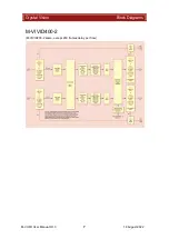
Page 7: ...Crystal Vision Block Diagrams M VIVID User Manual R1 3 6 18 August 2022 2 Block Diagrams M VIVID800...

Page 8: ...Crystal Vision Block Diagrams M VIVID User Manual R1 3 7 18 August 2022 M VIVID400 2 M VIVID200 2 same except 200 frames delay per flow...

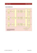
Page 9: ...Crystal Vision Block Diagrams M VIVID User Manual R1 3 8 18 August 2022 M VIVID100 3...

Page 10: ...rt the card by pushing the white handle on the card edge being careful to ensure the card is inside the guide rails Remove it by pulling the metal hook Do not force the card if resistance is met as th...

Page 11: ...0GbE video over IP D Type VR06 only No connection No connection No connection The VR07 provides dual relay bypass protection when M VIVID200 2 M VIVID400 2 and M VIVID800 are used with both SDI inputs...

Page 12: ...ved and transmitted using the VR04 VR06 VR07 10GbE network interface connections VR06 provides two network interfaces while the VR04 and VR07 provide four A typical usage case is to use Eth 1 interfac...

Page 13: ...ble to assign all flows to the same interface Flow Inputs Eth 1 1 Primary IP Input 1 Eth 2 1 Protect IP Input 1 Eth 1 2 Primary IP Input 2 Eth 2 2 Protect IP Input 2 Flow Outputs Eth 1 3 Primary IP Ou...

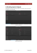
Page 14: ...VIVID User Manual R1 3 13 18 August 2022 4 2 Enabling Inputs Outputs By default M VIVID inputs and outputs are disabled Use the Enable control within the Input and Output menus to enable them M VIVID...

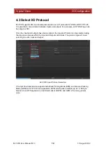
Page 15: ...the inputs and outputs have been enabled the required Protocol can be selected using the drop down menus within the Input and Output control tabs The protocol type will need selecting for each input...

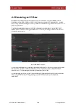
Page 16: ...VIVID configured to receive Input 1 using SMPTE ST 2022 7 protocol When selecting ST 2022 7 it is necessary to configure both the Network In and Protect Network In M VIVID Input 1 Flow In The controls...

Page 17: ...tions The following example shows an M VIVID configured to transmit Output 1 using ST 2110 20 GPM Protect protocol When selecting a protect protocol it is necessary to configure both the Network Out a...

Page 18: ...quired a valid SSRC Synchronisation source identifier can be entered otherwise left blank or set to 0 will accept all When transmitting ST 2110 the required payload type value should be set The value...

Page 19: ...time input has been present Format Read only text showing video format e g 1920x1080i 50Hz Video black LED Yellow if input is full frame black otherwise off Video frozen LED Yellow if input is frozen...

Page 20: ...ent LED Yellow when audio channels silent 93dBFS trigger point otherwise off The equivalent output status is also provided for video enabled video present video format video black video frozen audio g...

Page 21: ...enabled otherwise off Present LED Green when input is present otherwise off Error LED Red if lost or duplicate packets detected at input otherwise off Input flow network statistics Flow Statistics Pr...

Page 22: ...18 August 2022 Network In Protect Network In pkts Lost Number of lost packets Duplicate Number of duplicate packets Min gap Minimum gap between packets nSec Max gap Maximum gap between packets nSec M...

Page 23: ...400 frames delay per channel M VIVID800 single channel with up to 800 frames delay The video delay is adjustable in one frame increments Use the Output Output Enable menu to apply the delay Output fr...

Page 24: ...l channel M VIVID400 2 M VIVID200 2 and triple channel M VIVID100 3 feature independent video delay on each of the outputs Default routing is 1 1 2 2 and 3 3 However it is possible to route one input...

Page 25: ...me reference clock It is not possible to lock different outputs to different clocks Inputs are not required to be the same frame rate as the chosen reference It is possible for example to input 59 94H...

Page 26: ...rity reference source upon its return Active source Read only text showing which reference source is in use Force relock Returns to priority reference source if auto relock is not enabled PTP Configur...

Page 27: ...er PTP clock is configured correctly e g 8 packets a second and whether there are any packets missing which could indicate a network issue 7 2 Output timing The output timing controls adjust the offse...

Page 28: ...Sub frame adjustment of output timing relative to reference source Format to modify Independently adjust output timing for each video format Apply to all formats Select to apply the output timing adj...

Page 29: ...ped TPN transmission As per SMPTE ST 2022 transmission TPNL transmits the packets evenly spaced throughout the duration of each entire video frame but starting one line after the first Start of Frame...

Page 30: ...ps provide an Input Format control If set to All any input format present is deemed valid If set to a single format any input format present which does not match the selected format is deemed invalid...

Page 31: ...lowing internal test patterns are provided which when enabled replace the outgoing video content with the selected test pattern Internal Test Pattern option 9 3 Audio mute Embedded audio present in SD...

Page 32: ...utput network video Destination address should be the IP address of the downstream Ethernet Interface you want to transmit to The example below shows that rather than transmitting using a multicast ad...

Page 33: ...If set to 0 0 0 0 it will accept any source transmitting to its virtual interface IP address This is acceptable if it is known only one device at a time will be transmitting to it Alternatively the S...

Page 34: ...ted on GUI 11 2Errors in the IP flow s video content Check the Ignored packets count on the Ethernet Interfaces tab of GUI is incrementing in no more than values of 10s Incrementing in values of 100s...

Page 35: ...nded for separating main and protect video flows associated with the IP input output Multicast and unicast addresses are supported on a single network interface or can be divided across multiple inter...

Page 36: ...ts one per channel M VIVID800 Up to two 3Gb s or HD or SD video over IP outputs Any of the 10GbE IP network interfaces can be used to provide a protected output for SMPTE ST 2022 7 or ST 2110 seamless...

Page 37: ...application is to cleanly live switch the input of a single channel video delay without any output signal disturbance The setting for this would be Input 1 to Output 1 cleanly followed by Input 2 to...

Page 38: ...525i 1080i59 94 1080i60 1080p29 97 1080p30 1080PsF30 2048x1080p30 2048x1080PsF30 2048x1080p29 97 2048x1080PsF29 97 4 seconds 720p50 1080p50 3 33 seconds 720p59 94 720p60 1080p59 94 1080p60 1080PsF29...

Page 39: ...s Grey Vertical Steps Luma Horizontal Ramp Luma Vertical Ramp Cycle Colour Checker Board or Colour Square or to freeze the picture This is independently adjustable on each output AUDIO MUTE CONTROL Th...

Page 40: ...ted the card will automatically relock when a lost reference is restored Selecting Force lock with Auto relock disabled will force the synchroniser to relock after a reference is restored and can be a...

Page 41: ...l 8 Silence group 3 channel 9 Silence group 3 channel 10 Silence group 3 channel 11 Silence group 3 channel 12 Silence group 4 channel 13 Silence group 4 channel 14 Silence group 4 channel 15 Silence...

Page 42: ...offset and sync period REMOTE CONTROL Software VisionWeb Control is available via the web server on the frame and allows control and monitoring using a standard web browser on a computer tablet or ph...

Reviews: