POWER SUPPLY
INSTALLATION
The power supply is mounted above the cell assembly and flush to a wall
with the fastener provided. It is preferable that the power supply, as all pool
filtration equipment, is installed in a weatherproof location, but well
ventilated.
The power supply must be mounted no further than 1.5 metres from the
chlorinator cell, and positioned so as easy access is available to the
controls/time clock.
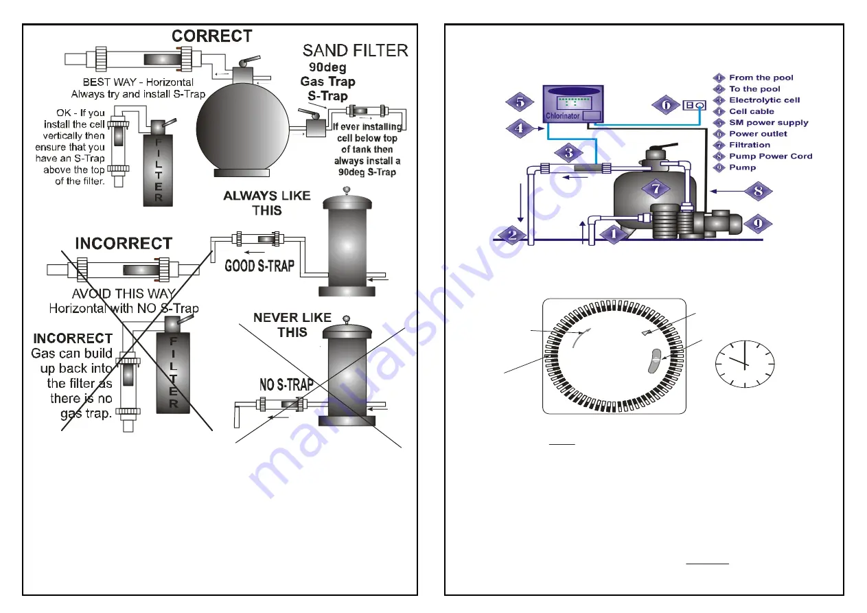
CHLORINATOR
INSTALLATION
Chlorinator must be installed according to the following instructions
CELL HOUSING
INSTALLATION
Caution: Cell must be installed correctly as per instructions:
1.Clock setting
.
NOTE: The above time is set to 10:00pm (i.e. 22H00)
2.Timer setting
NOTE: The above example is set to run from 10AM to 1PM
(3hours). All pins from 10 to 13 on the Dial will be extended out
OPTIONAL) BYPASS SWITCH.
3. Center Position:
Upper Position ( ):
Lower Position (O):
. Be sure to turn the “TIME DIAL” in the Direction
of the arrow.
turn in the reverse direction!
Line up the correct time of Day on the DIAL with the POINTER .
Each HOUR is divided into 4 x 15 Minute divisions (4x1/4 Hour)
. Set ON Times by moving DIAL SWITCHES to the
outer edge. Each SWITCH represents 1/4 Hour(15min) running.
For one hour of running 4 switches will be set to the outer edge.
(
This is the normal Timer Position(Automatic).
In this position the timer will operate as normal with automatic
switching on during the time set by the DIAL SWITCHES
In this position the TIMER is
regardless of the SWITCH settings.
In
Do not
always ON
I
this Position the TIMER is
regardless of the SWITCH settings.
always OFF
DIAL POINTER
TIME DIAL
Direction Arrow
BYPASS SWITCH
GRASSLIN
1
2
24
3
4
5
6
7
8
9
10
1 1
12
13
14
15
16
17
18
1
9
2
0
21
22
23
DIAL SWITCHES
The timer on the
left s set at 22H00.
i.e. 10:00pm on a
watch as per above.
8. MECHANICAL TIMER SETUP PROCEDURE
II
O


