8
V5-02-2010
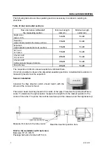
The following table shows the equalising sections necessary in relation to existing ob-
structions:
INSTALLATION DESCRIPTION
Flow obstruction
in front of
the measuring section
Minimum length
inlet (L1)
Minimum length
outlet (L2)
Slight curve
(bend < 90°)
12 x D
5 x D
Reduction
(pipe narrows towards the meas. section)
15 x D
5 x D
Expansion
(pipe expands towards the meas. section)
15 x D
5 x D
90° bend
or T piece
15 x D
5 x D
2 bends á 90°
on one level
20 x D
5 x D
2 bends á 90°
3-dimensional change of direction
35 x D
5 x D
Shut-off valve
45 x D
5 x D
Table of inlet and outlet sections
The respective minimum values required are indicated here.
If it is not possible to observe the stipulated equalising sections, considerable deviations in
measuring results must be expected.
Sensor installation
Hint for the installation with ball valve:
Ball valve R 1/2“, DN 15
Passage ball valve minimum Ø15 mm
Consider the flow direction which should match with the
arrows at the connector head.
Measure from here to the tube center
Read the insertion position here
The sensor head must be placed in the centre of the pipe. Therefore the probe shaft has a
scale. To determine the right position measure the length from the marked position to the
centre of the tube. The probe then will be inserted up to this measure and then tightened up.
mm
Summary of Contents for VA 400
Page 27: ...27 V5 02 2010 DECLARATION OF CONFORMITY...
Page 28: ...28 V5 02 2010 DECLARATION OF CONFORMITY...
Page 29: ...29 V5 02 2010 NOTES...
Page 30: ...30 V5 02 2010 NOTES...
Page 31: ...31 V5 02 2010 NOTES...


