9
V5-02-2010
ASSEMBLY INSTRUCTIONS
Assembly instructions
Safety information must be observed.
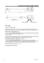
Assembly is carried out by inserting the connection thread (1/2“ thread, SW 27) into the
connection piece. The sensor is then inserted to the required immersion depth and aligned
according to the direction of air flow. A depth scale engraved on the probe tube, a flow
alignment arrow and an aligning device will be of help to you. Once the sensor has been
aligned, the adapter sleeve must be tightened with the stipulated torque (SW 17).
Attention: Alignment of the sensor must not be modified when tightening the connection
thread and adapter sleeve. In this case please check the immersion depth and alignment
again and correct if necessary. The angular deviation should not be greater than ± 2° in re-
lation to the ideal position as otherwise the measuring accuracy will decrease.
Commissioning
The valid measuring range and delivery configuration are programmed by the manufacturer
on the basis of the user’s specifications.
The
stationary
flow and air consumption measuring devices from the VA 400/ DS 300 se-
ries function according to the “plug and play” principle. The device is ready for operation as
soon as the power supply is connected.
.
Summary of Contents for VA 400
Page 27: ...27 V5 02 2010 DECLARATION OF CONFORMITY...
Page 28: ...28 V5 02 2010 DECLARATION OF CONFORMITY...
Page 29: ...29 V5 02 2010 NOTES...
Page 30: ...30 V5 02 2010 NOTES...
Page 31: ...31 V5 02 2010 NOTES...


