background image


Operation 

VA 500  English V1.16 


Seite 34 von 52 

8.3.2.2 

Modbus TCP (Optional)  


The Flow sensors VA 500 comes optional with a Modbus TCP Interface  
(HW Interface:M12 x 1 X-coded connector).


Device supports with this option the Modbus TCP protocol for communication with SCADA 
systems. TCP port is set to 502 by default. Port can be changed at the sensor or using PC 
Service Software  
 
Modbus device address (Unit Identifier) can be set in the range of 1- 255. 
Specification and description of the Modbus protocol is free to download on: 

www.modbus.org

.  

 
Supported Modbus commands (functions):  
Command 

Code  

Description  

Function Code 

3  

(Read holding register)  

Function code 

16  

(Write multiple registers) 


For more details, please see 

VA 5xx Modbus RTU_TCP Installation V1.04


Settings 

 Network Setup 


8.3.2.2.1  Network Setup DHCP 

Settings 

 Network Setup Settings 

 IP Address 


Here you can set up and made a connection, with 
or without 

DHCP

, to a computer. 


Remark: 

With activated 

DHCP

 the automatic integration of 

the sensor in an existing network is possible, 
without a manual configuration. 
 
Storing of settings by pressing 

“Save


Summary of Contents for VA 500

Page 1: ...h V1 16 Seite 1 von 52 EN English Instruction manual Consumption sensor VA 500 with Display 4 20 mA and Pulse output galv isolated Stationary and mobile flow and consumption measurement for compressed air and gases ...

Page 2: ...ect functioning of the VA 500 are only guaranteed in case of careful observation of the described instructions and notes Sales Office South Geschäftsstelle Süd Zindelsteiner Str 15 D 78052 VS Tannheim Tel 49 0 7705 978 99 0 Fax 49 0 7705 978 99 20 Mail info cs instruments com Web http www cs instruments com Sales Office North Geschäftsstelle Nord Am Oxer 28c D 24955 Harrislee Tel 49 0 461 700 20 2...

Page 3: ...00 11 4 3 1 welded nipple with ball valve 11 4 3 2 Spot drilling collar with ball valve 11 4 4 Installation of the Sensor 12 4 4 1 Mounting VA 500 onto the ball valve 12 4 5 Display Head Position 12 5 Measuring ranges 13 5 1 Maximum Flow Ranges Low Speed 14 5 2 Maximum Flow Ranges Standard 16 5 3 Maximum Flow ranges Max speed 18 5 4 Maximum Flow ranges High speed 20 6 Dimension 22 7 Electrical wir...

Page 4: ...p DHCP 34 8 3 2 2 2 Network Settings static IP 35 8 3 2 2 3 Modbus TCP Settings 36 8 3 2 3 Modbus Settings Register 2001 2005 37 8 3 2 4 Values Register 1001 1500 37 8 3 3 Pulse Alarm 39 8 3 3 1 Pulse output 39 8 3 4 User Setup 40 8 3 4 1 Password 40 8 3 4 2 Language 40 8 3 4 3 Display Touch 41 8 3 5 Advanced 41 8 3 6 4 20mA 42 8 3 7 VA 500 Info 44 8 4 MBus 45 8 4 1 Default Settings communication ...

Page 5: ...s they may cause faulty The values of the inlet and outlet sections must not fall below the specified minimum values as this causes increased deviations in the measuring results The manufacturer cannot be held liable for any damage that occurs because of non observance or non compliance with these instructions Should the device be tampered with in any matter other than a procedure which is describ...

Page 6: ...iation for Gas and Water admission however it can be used for natural gas A DVGW admission is not mandatory The consumption sensor VA 500 corresponds with the latest state of technology and can generally be used for burnable and non burnable gases For the use in e g natural gas the sensor will be calibrated in natural gas The calibration protocol inspection certificate is included in the scope of ...

Page 7: ...e in m h m min etc Counter in m l cf as well as pulse output 1 pulse per m l cf are calculated according to the set diameter Please take the analogue value for flow rate 4 20 mA from the tables on pages 14 to 19 4 mA always corresponds with the starting value 0 m h 0 m min The final value 20 mA can be taken from the tables on pages 14 to 19 Example VA 500 Standard 1 with inner diameter 25 0 mm 4 m...

Page 8: ...ated Display showing Flow consuption velocity and temperature Input inner tube diameter via display keys Units free selectable m h m min l min l s kg h kg min kg s cfm Modbus RTU RS485 Interface Analogoutput 4 20mA Pulse output galv isolated CS Instruments Service Software Analogaoutput 4 20 mA scaleabler Selection of gas type Air Nitrogen Argon Nitrous oxide CO2 Oxygen Natural gas Read out Servic...

Page 9: ...nt Sensor Pt45 Pt1000 Measuring medium Air gases Operating temperature 30 100 C probe tube 20 70 C housing Operating pressure up to 50 bar Power supply 18 to 36 VDC Power consumption max 5W Digital output RS 485 Modbus RTU Analog output 4 20 mA see tables page 13 18 max burden 500 Ohm Pulse output pulse output potential free dry contact passive max 48Vdc 150mA 1 pulse pro m resp pro l Valency adju...

Page 10: ...y long straight and without any obstructions such as edges seams curves etc Therefore it is necessary to ensure the recommended inlet and outlet runs Table Inlet Outlet runs Flow obstruction before the measurement section Min length Inlet run L1 Min length Outlet run L2 Slight curve elbow 90 12 x D 5 x D Reduction Pipe narrows to the measurement section 15 x D 5 x D Expansion Pipe expands to the m...

Page 11: ... 3 1 welded nipple with ball valve 4 3 2 Spot drilling collar with ball valve In case the system could not be shut down means to be set depressurized there could be used the CS spot drilling collar Order No 0530 1108 and drilling jig Order No 0530 1108 to drill through the ball valve Important Ensure that the system is in shut down ie depressurized Note for installation with ball valve Ball valve ...

Page 12: ...ulated torque of 20 30Nm SW 17 Attention Alignment of the sensor must not be modified when tightening the connection thread and adapter sleeve In this case please check the immersion depth and alignment again and correct it if necessary The angular deviation should not be greater than 2 in relation to ideal position as otherwise the measuring accuracy will decrease Calculation mounting depth Align...

Page 13: ... 5 3 Example Pipe 1 Inner diameter 25mm Measuring range Analogoue output Scaling Low Speed 0 65 9 m h 4mA 0 m h 20mA 65 9 m h Grundversion Standard 0 122 2 m h 4mA 0 m h 20mA 122 2 m h Max Version 0 243 88 m h 4mA 0 m h 20mA 243 88 m h Highspeed Version 0 295 30 m h 4mA 0 m h 20mA 295 30 m h For changing the inner pipe diameter and adjusting the 4 20mA scaling please refer to chapter Operation Ple...

Page 14: ...5 184 5 116 8 108 5 112 6 115 7 69 8 50 36 0 143 6 132 0 224 5 142 1 132 0 137 0 140 8 84 9 50 36 3 146 0 134 4 228 6 144 7 134 4 139 4 143 4 86 5 50 1 1 2 39 3 172 7 159 0 270 3 171 1 159 0 164 9 169 6 102 2 50 40 0 179 3 164 9 280 4 177 5 164 9 171 0 175 9 106 0 50 41 9 197 8 181 0 307 7 194 8 181 0 187 8 193 0 116 4 50 43 1 210 0 193 1 328 4 207 8 193 1 200 3 206 0 124 2 50 45 8 238 3 219 1 372...

Page 15: ...2966 8 2756 5 2860 0 2940 9 1773 0 50 182 5 3949 8 3622 2 6160 3 3898 5 3622 2 3758 3 3864 6 2329 8 50 190 0 4286 4 3926 1 6677 0 4225 6 3926 1 4073 5 4188 7 2525 2 50 8 200 0 4755 1 4355 4 7407 2 4687 6 4355 4 4519 0 4646 8 2801 3 50 206 5 5069 0 4643 1 7896 5 4997 3 4643 1 4817 5 4953 7 2986 4 50 10 250 0 7412 1 6813 4 11587 6 7333 2 6813 4 7069 3 7269 3 4382 3 50 260 4 8060 9 7400 9 12586 7 796...

Page 16: ...218 8 201 1 342 0 216 5 201 1 208 7 214 6 129 4 92 7 36 0 266 3 244 8 416 3 263 4 244 8 254 0 261 1 157 4 92 7 36 3 270 7 249 2 423 8 268 2 249 2 258 5 265 9 160 3 92 7 1 1 2 39 3 320 1 294 7 501 2 317 2 294 7 305 7 314 4 189 5 92 7 40 0 332 5 305 7 519 8 329 0 305 7 317 1 326 1 196 6 92 7 41 9 366 7 335 5 570 5 361 1 335 5 348 1 357 9 215 8 92 7 43 1 389 4 358 0 608 8 385 3 358 0 371 4 381 9 230 ...

Page 17: ...6 5500 5 5110 6 5302 5 5452 5 3287 1 92 7 182 5 7323 6715 6 11421 2 7227 9 6715 6 6967 8 7164 9 4319 4 92 7 190 0 7947 7278 9 12379 2 7834 2 7278 9 7552 3 7765 8 4681 7 92 7 8 200 0 8816 8074 9 13733 0 8690 9 8074 9 8378 2 8615 1 5193 7 92 7 206 5 9398 8608 3 14640 1 9265 0 8608 3 8931 6 9184 2 5536 8 92 7 10 250 0 13742 12632 1 21483 4 13595 8 12632 1 13106 5 13477 2 8124 8 92 7 260 4 14945 13721...

Page 18: ...2 2 401 5 416 4 428 2 258 2 185 0 36 0 531 48 488 7 830 8 526 0 488 7 506 8 521 1 314 3 185 0 36 3 541 06 497 5 845 8 535 5 497 5 515 9 530 5 320 0 185 0 1 1 2 39 3 639 84 588 3 1000 2 633 3 588 3 610 1 627 4 378 4 185 0 40 0 663 68 610 2 1037 5 656 9 610 2 632 8 650 8 392 5 185 0 41 9 728 41 669 7 1138 7 720 9 669 7 694 5 714 2 430 7 185 0 43 1 777 34 714 7 1215 2 769 4 714 7 741 2 762 2 459 7 18...

Page 19: ...10581 1 10881 0 6562 2 185 0 182 5 14581 94 13407 5 22795 1 14432 2 13407 5 13904 1 14298 2 8623 0 185 0 190 0 15805 08 14532 1 24707 2 15642 8 14532 1 15070 4 15497 5 9346 4 185 0 8 200 0 17533 48 16121 3 27409 1 17353 4 16121 3 16718 4 17192 3 10368 4 185 0 206 5 18691 68 17186 2 29219 6 18499 7 17186 2 17822 8 18327 9 11053 3 185 0 10 250 0 27428 75 25219 6 42877 8 27147 1 25219 6 26153 7 26895...

Page 20: ...23 1 486 3 504 2 518 6 312 8 224 0 36 0 643 52 591 8 1006 1 636 6 591 8 613 6 631 2 380 7 224 0 36 3 655 12 602 5 1024 2 648 1 602 5 624 7 642 5 387 5 224 0 1 1 2 39 3 774 73 712 5 1211 2 766 4 712 5 738 8 759 9 458 3 224 0 40 0 803 59 739 0 1256 3 795 0 739 0 766 3 788 2 475 3 224 0 41 9 881 96 811 1 1378 9 872 5 811 1 841 0 865 0 521 7 224 0 43 1 941 21 865 6 1471 5 931 1 865 6 897 5 923 1 556 7...

Page 21: ... 12812 4 13178 3 7947 8 224 0 182 5 17655 97 16237 2 27603 2 17466 8 16237 2 16836 2 17317 0 10443 8 224 0 190 0 19136 96 17599 2 29918 6 18931 9 17599 2 18248 5 18769 6 11319 9 224 0 8 200 0 21229 73 19523 8 33190 4 21002 3 19523 8 20244 1 20822 2 12557 8 224 0 206 5 22632 08 20813 4 35382 8 22389 6 20813 4 21581 3 22197 6 13387 3 224 0 10 250 0 33211 03 30542 3 51921 9 32855 2 30542 3 31669 1 32...

Page 22: ...imension VA 500 English V1 16 Seite 22 von 52 6 Dimension 416 0 Standard Schaft 220mm 76 5 G ISO 228 1 SW 32 SW 27 75 0 220 mm Standard Optional 120 160 300 400 mm Ø11 7 Connector plug A Connector plug B ...

Page 23: ...odbus RTU A MBus MBus reverse polarity protected If no connection cable pulse cable is ordered the sensor will be supplied with a M12 connector plug The user can connect the supply and signal cables as indicated in the connection diagram M12 Connector plug View from back side terminal side Connector plug A M12 A coding Connector plug B M12 A coding 3 4 5 1 2 VB VB 4 20mA Grau Grey Blau Blue Weiss ...

Page 24: ...thernet optional PoE Connector plug B Connection cable M12 x coded 8 pole M12 x coded to RJ45 Data LINES 1 2 und 3 4 PoE LINES 5 6 und 7 8 2 8 1 3 5 4 6 7 M12 x 1 Connection cable Cat 6 PoE Power over Ethernet Connector plug B M12 X coded 8 pole Connector plug A ...

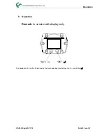
Page 25: ...Operation VA 500 English V1 16 Seite 25 von 52 8 Operation Remark In version with display only Up OK The operation of the VA 500 is done by the two capacitive key buttons Up und Enter ...

Page 26: ...W Version Modbus ID VA 500 Switching to pages 2 4 or back by pressing key VA 500 391 23 391 1 minutes 410 34 1 minute 91 32 82 46 AV Time Period for average value calculation could be changed under Sensor Setup Advanced AV Time After switching on the VA 500 the initialized screen is displayed followed by the main menu ...

Page 27: ...enu is password protected Selection of a menu item or to change a value is done with the key a final move to the chosen menu item or takeover of the value change needs the confirmation by pressing the key OK Factory settings for password at the time of delivery 0000 4 times zero If required the password could be changed at Setup User setup Password ...

Page 28: ...ith OK In order to change e g the unit first select by pressing key the field Units and then key OK Select with the key the correct unit and then confirm selection by pressing 2x OK Entering changing the diameter via button select the respective position and activate the position with the OK button By pressing the position value is incremented by 1 Complete with OK and activate next number positio...

Page 29: ...ection by pressing 2x OK Entering changing the consumption counter via button select the respective position and activate the position with the OK button By pressing the position value is incremented by 1 Complete with OK and activate next number position Confirm entry by pressing OK To make changes to the unit for the respective measurement value first select by pressing the field of the measurem...

Page 30: ...ence conditions Setup Sensor Setup Advanced Setup Sensor Setup Advanced Ref Pref Setup Sensor Setup Advanced Ref Temp Setup Sensor Setup Advanced Filtertime To make changes first select a menu with button and confirm selection by pressing OK In order to change e g the unit first select by pressing key the field Units and then key OK Select with the key the correct unit and then confirm selection b...

Page 31: ...nsor Setup Advanced AV Time Under item Filtertime an attenuation can be defined Input values of 0 10000 in ms are possible The time period for averaging can be entered here Input values of 1 1440 minutes are possible For average values see display window 3 4 ...

Page 32: ...h OK By pressing the position value is incremented by 1 Confirm the input with OK and activate next number position Leave menu with button Back Menüpunkt mit Taste anwählen und anschließend mit Taste OK auswählen With the low flow cut off activated the flow below the defined LowFlow Cut off value will be displayed as 0 m h and not added to the consumption counter For an input change of the value s...

Page 33: ... be released and set the internal DIP Switch to On Alternatively a 120R resistor can be installed in the plug between pin 2 and pin 4 It must be ensured that the connection plugs are still plugged and the gasket is installed correctly see also chapter 4 5 For changes e g the sensor ID first select by pressing key the field ID and then key OK Select the desired position by pressing the and select w...

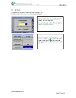
Page 34: ...5 Specification and description of the Modbus protocol is free to download on www modbus org Supported Modbus commands functions Command Code Description Function Code 3 Read holding register Function code 16 Write multiple registers For more details please see VA 5xx Modbus RTU_TCP Installation V1 04 Settings Network Setup 8 3 2 2 1 Network Setup DHCP Settings Network Setup Settings IP Address He...

Page 35: ...ress Subnet and Gateway selection keys must be selected and activated with OK The first data field of the selection in this case the IP address is then marked red Confirm with OK the corresponding input menu is opened By means of the next data field is changed Select the desired position with the key and activate it with the OK key Change the values with the key and accept the values with the OK k...

Page 36: ...ld ID and then key OK Select the desired position by pressing the and select with OK button Change values by pressing the values takeover by pressing OK Input for the port is done analogue By means of the button Byte Format it is possible to change the data format Word Order Possible formats are ABCD Little Endian and CDAB Middle Endian Saving the changes by pressing Save therefore select it with ...

Page 37: ...ndian 0xCDAB Middle Endian 8 3 2 4 Values Register 1001 1500 Modbus Register Register Address No of Byte Data Type Description Def ault Read Write Unit Comment 1101 1100 4 Float Flow in m h R 1109 1108 4 Float Flow in Nm h R 1117 1116 4 Float Flow in m min R 1125 1124 4 Float Flow in Nm min R 1133 1132 4 Float Flow in ltr h R 1141 1140 4 Float Flow in Nltr h R 1149 1148 4 Float Flow in ltr min R 1...

Page 38: ...sumption cf before comma x R 1299 1298 4 UInt32 Consumption Ncf before comma x R 1305 1304 4 UInt32 Consumption kg before comma x R 1311 1310 4 UInt32 Consumption kWh before comma x R 1347 1346 4 Float Velocity m s 1355 1354 4 Float Velocity Nm s 1363 1362 4 Float Velocity Ft min 1371 1370 4 Float Velocity NFt min 1419 1418 4 Float GasTemp C 1427 1426 4 Float GasTemp F Remark For DS400 DS 500 Hand...

Page 39: ...displayed The galvanically isolated output can be defined as pulse or alarm output Selection of field Relay Mode with key and change modus by pressing key OK For alarm output following units could be chosen kg min cfm ltr s m h m s F C and kg s Value defines the Alarm value Hyst defines the desired hysteresis and with Hi Lim or Lo Lim the alarm settings when the alarm is activated Hi Lim Value ove...

Page 40: ...word The required password length is 4 digits Please select with button a figure and confirm it with OK Repeat this 4 times With the last figure could be deleted Password input have to be inserted twice Confirmation of input password by pressing OK Factory settings for password at the time of delivery 0000 4 times zero Currently 4 languages have been implemented and could be selected with button C...

Page 41: ...ay brightness The actual adjusted backlight brightness is showed in the graph Backlight By activation Dimming after and entering a time a display dimming could be set With Rotate Screen the display information could be rotated by 180 By activation of Key Lock the operation of the sensor locked Unlocking the keyboard is only possible by restarting the sensor and calling the operating menu within th...

Page 42: ...ocity und Flow to the channel CH 1 To make changes first select the value item with button and confirm Moving between the different measurements values or to deactivate the 4 20mA with setting to unused by pressing OK To the selected measurement value a corresponding appropriate unit needs to be defined Select Unit with and open menu with OK Select required unit with and take over by pressing OK H...

Page 43: ... value settings Using CLR clears up the complete settings at once For Auto on the max scaling is calculated based on the inner tube diameter max measurement range and the reference conditions settings Take over of the inputs with Save and leaveing the menu with Back This determines what is output in case of an error at the analog output 2 mA Sensor error System error 22 mA Sensor error System erro...

Page 44: ... Info Setup Sensor Setup Info Run Time 2d 21h 23m 12s Vin 23 8V Temp 35 8 92 7 m s 600m h 20 C 53 1 mm 23 C 10 Here you get a brief description of the sensor data incl the calibration data Under Details you are able to see in addition the calibration conditions ...

Page 45: ...tted Value 1 with Unit Consumption m Value 2 with Unit Flow m h Value 3 with Unit Gas temperature C All Values could be changed preset in production or with CS Service software Order No 0554 2007 The Sensor offers two possibilities for coding the Value Informaition Field VIF Primary VIF The units and multiplier correspond to MBus specification 4 8 chapter 8 4 3 Plain text VIF units are transmitted...

Page 46: ...he next recalibration is recommended is internally entered When this date is reached a message appears in the display with the status message CAL Note The measurement will continue without interruption or restriction Direction When used in conjunction with a direction switch VA409 the status message Direction is displayed in case of opposite flow direction and no measurement may take place Status ...

Page 47: ...his message Internal Error the sensor has an internal read error on e g EEProm AD converter etc detected I Temp out of Range At media temperatures outside the specified temperature range the status message Temp out of Range occurs This temperature overshoot leads to incorrect measurement values outside the sensor specification Low Voltage 4 20mA For sensors with a galvanically isolated 4 20mA outp...

Page 48: ...year for the instrument VA 500 On request and additional payment calibration certificates could be issued The precision is given due to use DKD certified flow meters and verifiable 15 Warranty If you have reason for complaint we will of course repair any faults free of charge if it can be proven that they are manufacturing faults The fault should be reported immediately after it has been found and...

Page 49: ...Conformity VA 500 English V1 16 Seite 49 von 52 ...

Page 50: ...Notes VA 500 English V1 16 Seite 50 von 52 ...

Page 51: ...Notes VA 500 English V1 16 Seite 51 von 52 ...

Page 52: ...Notes VA 500 English V1 16 Seite 52 von 52 ...

Reviews: