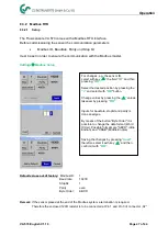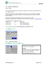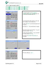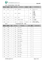
Wiring
VA 570 English V1.19
Page 16 of 44
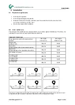
7 Connection diagram
7.1
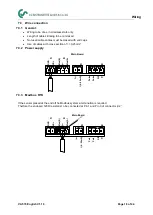
Cable glands - clamping ranges
For ensuring the tightness and strain relief, connector cables with the following diameters must be
used.
VA570 Standard clamping range :
Ø5-9mm
VA570 Ex clamping range:
Ø5-10mm
7.2
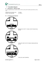
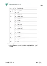
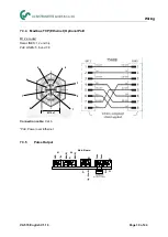
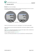
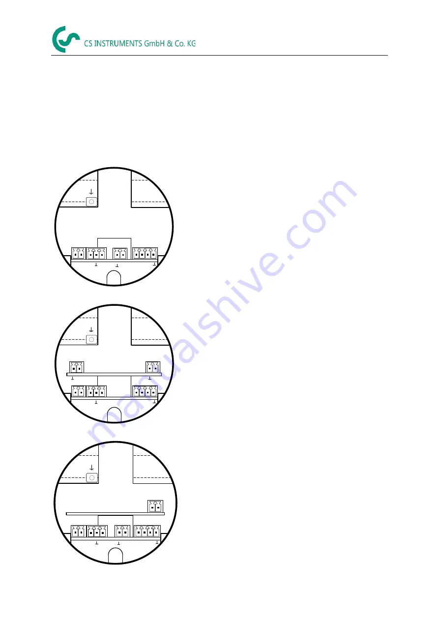
Connector pin assignment
P
u
ls
e
1
2
I
(4
-2
0
m
A
)
X1
X2
X3
1
2
G
N
D
V
B
+
1
2
3
M
o
d
(A
)
1
2
3
4
P
u
ls
e
D
IR
Main Board
M
o
d
(B
)
X4
Standard version with 1x analogue output (not galvanically
isolated)
P
u
ls
e
1
2
I (4-20mA)
1
2
X1
X2
X4
X6
X5
I (4-20mA)
1
2
G
N
D
V
B
+
1
2
3
M
o
d
(A
)
1
2
3
4
P
u
ls
e
D
IR
Main Board
M
o
d
(B
)
Option Board 4-20mA
Version with option board 2x analogue outputs galvanically
isolated
P
u
ls
e
2
1
X1
X2
X4
K1
MBUS
1
2
G
N
D
V
B
+
1
2
3
M
o
d
(A
)
1
2
3
4
P
u
ls
e
D
IR
Main Board
M
o
d
(B
)
Option Board MBus
I
(
4
..
.2
0
m
A
)
X3
Version with option board MBus


