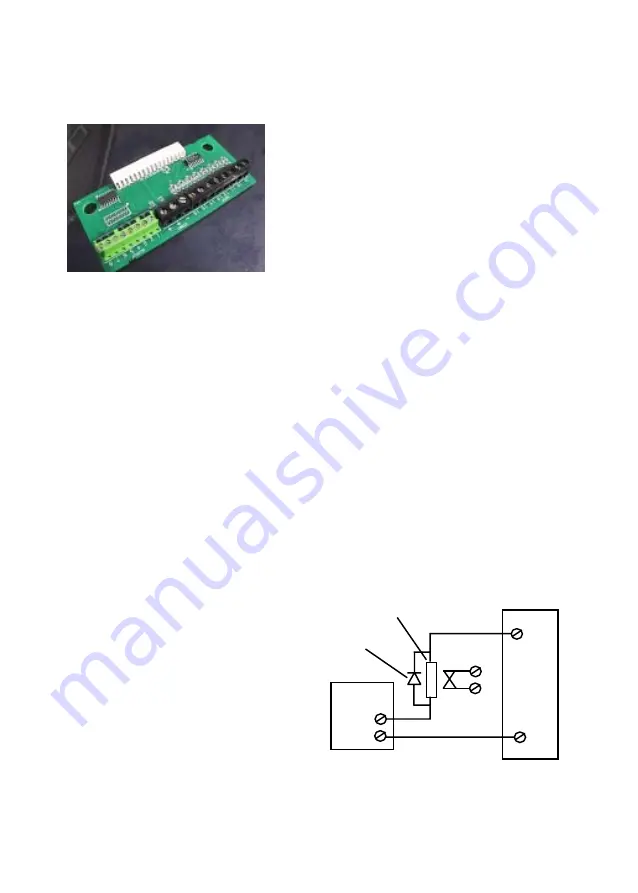
The CS1050 Expander Board
The CS1050 is a plug-on board that adds an additional 8 inputs and 8 outputs
to the CS1000 and CS2000 range of DualComs.
Fig 5b
o/p
0 v
Relay
Diode
CS1050
Power
Supply
+VE
0 v
5. The DualCom NVM will need to be
programmed for ‘16 channels’ en-
abled. Your ARC may provide a pro-
gramming service. Alternatively,
contact the CSL Technical Support
Desk. See page 9.
All of the normal input programming
options apply to the CS1050 Ex-
pander.
14
These are: Positive applied / removed triggering, self learning, restore re-
porting, open/close reporting, radio failure report and PSTN failure report.
3. Connect the triggering inputs to the INPUT terminals labelled 9 to 16, as
required. See page 12 and Appendix 2.
4. Connect the outputs to the OUTPUT terminals, labelled 1 to 8, as required.
These outputs are ‘open collector pull-down’ to 0v. Each will supply up to
50mA and may operate lights or relays with a supply up to +28 volts. Where
relays are connected, they should be fitted with a diode across their coil to
reduce ‘back EMF’ voltages. See Fig 5b.
Note: If you use a separate Power Supply, remember to connect the 0v
terminals of
all
of the parts of the system.
The CS1050’s outputs can be remotely controlled via the radio path using
the CS2054 Programmer software and by SMS messages from a mobile
phone. See page 33.
Fig 5a
To install:
1. Remove power to the DualCom when fit-
ting or removing the CS1050 Expander
board.
2. Slide the CS1050 Expander into the two
guides on the DualCom with the white con-
nector towards the DualCom board. Push
the CS1050 down to ensure it connects
fully. See Figs 1 and 2.


