UniCAN 3 – Installing the device
Installation Manual
9
Version 01.00 // 2018
3.6 Connectors
3 6 1 Power supply and Ethernet
UniCAN 3 data loggers are designed for an operating voltage of 8 V DC (–10 %) to 32 V DC (+10 %). The
connection to power supply and Ethernet is made using a 7-pole LEMO 0B socket on the back of the
housing (see Fig. 3-1,
⑦
“Power supply, Ethernet”).
NOTE!
i
The shield and GND of a signal line, as well as the housing of the data logger, are elec-
trically connected to the power GND of the supply line.
There is a risk of damage from short-circuit current or compensating current.
)
Never connect the supply voltage to shield, GND or housing.
)
Ensure that shield, GND and housing are held on the same potential.
Image
Pin
Signal
Description
1
2
3
4
5
6
7
1
30 (Power +)
Power supply, plus
2
15 (Ignition)
Control signal for switching the device on and off
3
TxN_P
Ethernet transmitter, plus
4
TxN_N
Ethernet transmitter, minus
5
RxN_P
Ethernet receiver, plus
6
RxN_N
Ethernet receiver, minus
7
31 (Power GND)
Power supply, ground
Housing
Shield
Cable shield
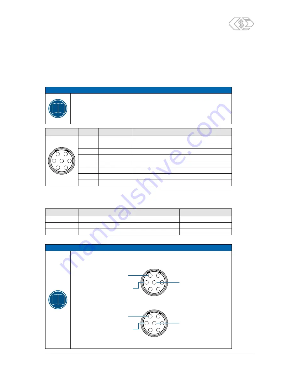
Tab. 3-6: “Power supply, Ethernet” socket pin assignment (back view of the device)
The following table shows the assignment of the signals to the wire colors for a K212 cable (LEMO 0B,
7-pole to open cable end):
Signal
Description
Wire color
30 (Power +)
Power supply, plus
Red
31 (Power GND) Power supply, ground
Black
15 (Ignition)
Control signal for switching the device on and off
Yellow
Tab. 3-7: K212 signal cable: signal to wire color assignment
NOTE!
i
To prevent data loss in case of a sudden interruption of the power supply, we recommend
switching the device on and off with the ignition signal (terminal 15). Please use the
following connection:
1
2
3
4
5
6
7
Ignition on/off
(terminal 15)
Steady plus
(terminal 30)
Ground
(terminal 31)
If no ignition signal is available, or the device is to be switched on and off by Wake-on-CAN
or a set alarm instead, use the following connection:
1
2
3
4
5
6
7
Ground (terminal 31)
or unconnected
Steady plus
(terminal 30)
Ground
(terminal 31)
Make sure that the device switches itself off using a suitable configuration while it is
still supplied with power (steady plus) to avoid data loss.


