UniCAN 3 – Installing the device
Installation Manual
10
Version 01.00 // 2018
i
If only a switched power supply is available, we recommend additional buffering
using the
CSM power control module (PCMM)
.
For additional information, please contact the sales department.
3 6 2 CAN interface
D-SUB-HD sockets, 15-pole (device)
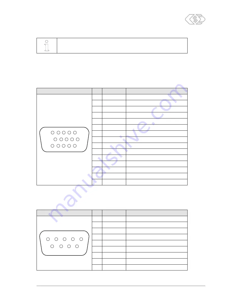
Depending on the version, the UniCAN 3 features up to three 15-pole D-SUB-HD sockets (see Fig. 3-1,
⑩
“CAN interfaces”, from left to right: CAN 1–4, CAN 5–8, CAN 9–12). The pin assignment of the first
(left-hand) socket is as follows, whereas the other two sockets correspond to the same scheme:
Image
Pin
Signal
Description
1
11
5
15
6
10
1
CAN1H
CAN 1 High
2
CAN2H
CAN 2 High
3
CAN3H
CAN 3 High
4
CAN4L
CAN 4 Low
5
not assigned
—
6
CAN1L
CAN 1 Low
7
CAN2L
CAN 2 Low
8
CAN3L
CAN 3 Low
9
not assigned
—
10
CAN4H
CAN 4 High
11
CAN1GND
CAN 1 Ground
12
CAN2GND
CAN 2 Ground
13
CAN3GND
CAN 3 Ground
14
CAN4GND
CAN 4 Ground
15
not assigned
—
Tab. 3-8: Pin assignment of the first (left-hand) 15-pole D-SUB-HD CAN socket (back view of device)
D-SUB plug, 9-pole (K201 cable)
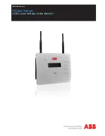
On the CSM K201 cable, four CAN connections are routed on separate 9-pole D-SUB plugs with a CiA-
compatible pin assignment.
Image
Pin
Signal
Description
1
5
6
9
1
not assigned
—
2
CAN L
CAN Low
3
CAN GND
CAN Ground
4
not assigned
—
5
Shield
Shield / Housing
6
not assigned
—
7
CAN H
CAN High
8
not assigned
—
9
CAN PWR
CAN power (not required)
Tab. 3-9: Pin assignment of a 9-pole D-SUB plug (K201 cable)


