Connection
Description
Power supply
Power
consumption
X1
Power supply 230V AC (L, N, and 6 x PE)
230V 50Hz
200 VA
X2
Zero-potential malfunction reporting relay
42V
1A
X3
External water sensor (zero current)
-
-
1
Fan connection 230V AC
230V 50Hz
65 VA
2
Water pump 230V AC
230V 50Hz
25 VA
3
Rinsing pump 230V AC
230V 50Hz
25 VA
4
Magnetic valve 230V AC
230V 50Hz
10 VA
5
UV lamp 230V AC
230V 50Hz
6 VA
X9
Water sensors, 10 litre to 50 litre
-
-
The fan can be set by the remote control unit at any
of five speeds (4 set speeds and one automatic func-
tion). The required speed can be set with the Fan
button (see above) on the remote-control unit. When
the Fan button is pressed the bar indicator starts to
flash. Pressing the + or the
– side increases or de-
creases the fan output. The automatic function ena-
bles the appliance to control its own speed depending
on the output required. It does this by measuring the
changes in atmospheric humidity and increasing or
decreasing the fan speed accordingly. To activate the
automatic fan, press the
„-” side of the Fan button
and hold it down until the last bar has disappeared
from the indicator and the red diode with the fan
symbol has gone out. To deactivate it, simply increase
the fan speed with the Fan button until the red diode
comes on again.
Changing the fan
m
Before doing any work on the appliance,
always make sure it is unplugged from the
wall socket.
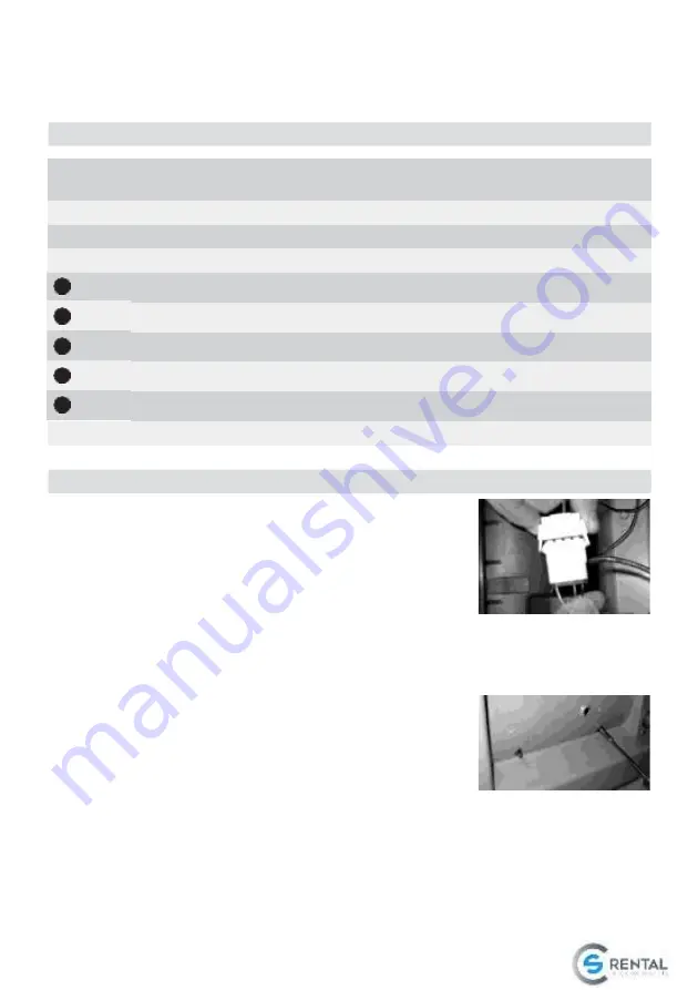
1. Loosen and pull
the fan plug by
pressing the plug
clamps.
2. Set the centre
part of the B 500
aside and loosen
the three boltings. Mind that the fan does not fall
out after the screws are loosened.
3. Take the fan out.
4. Insert the new fan
and attach the
screw threads to
the vibration ab-
sorber by plugging
them through the
holes in the centre plate.
5. Tighten the fan and plug the appliance in again.
12. Fan settings
11. Connections on the circuit board
Summary of Contents for B500
Page 1: ......
Page 15: ...22 Construction ...


