English |
25
2 610 A15 112 • 12.8.09
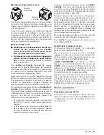
Aligning the Rotational Plane in the
Vertical Position
When the measuring tool is in the vertical position, it
is possible to rotate the laser point, laser line or rota-
tional plane around the Y-axis for easy sighting out or
parallel alignment.
Rotation is possible within a range of
±
10 %.
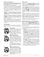
After switching on in vertical position,
“CCW CW/
SWEEP POS”
(rotation in counterclockwise or clock-
wise direction/line positioning) is indicated on the dis-
play. Align the rotational plane by pressing selection
button
8
above
“CCW”
(rotation in counterclockwise
direction) or selection button
4
above
“CW”
(rotation in
clockwise direction).
To exit the menu, press function-mode button
7
.
The alignment of the rotational plane is retained
regardless of whether rotational operation, line opera-
tion or point operation is set afterwards.
To change the alignment of the rotational plane,
switch back to the
“SELECT/SWEEP POS”
menu
by pressing function-mode button
7
.
Automatic Levelling
The automatic levelling and the shock-warning func-
tion can be switched on and off on the measuring tool.
Press function-mode button
7
until
“SELECT/
AUTOLEVEL”
(selection/automatic levelling) is indi-
cated on the display. Then press the left selection but-
ton
8
. The setting indicated at the top of the display is
active and can be changed by pressing the left selec-
tion button.
The following settings are possible:
–
“ADS”
(shock-warning function): Automatic level-
ling and shock-warning function switched on.
–
“ON”
: Automatic levelling switched on, shock-
warning function switched off.
–
“OFF”
: Automatic levelling and shock-warning
function switched off.
When the desired setting is indicated, press the func-
tion-mode button
7
to save the setting and to exit the
menu.
Shock-warning Function (“ADS”)
The measuring tool has a shock-warning function;
after position changes or shock to the measuring tool,
or in case of ground vibrations, it keeps the measuring
tool from levelling in at changed heights, and thus pre-
vents vertical errors.
Note:
When the measuring tool is in horizontal posi-
tion, only not-inclined axes are monitored. When two
axes are inclined, the shock-warning function is deac-
tivated. When one axis is inclined and the other not,
the not-inclined axis is monitored. Position changes
exactly alongside the inclined axis are not detected.
When factory set, the shock-warning function is acti-
vated after switching on the measuring tool. The shock
warning is activated approx. 60 s after switching on the
measuring tool or switching on the shock-warning func-
tion.
When the levelling-accuracy range is exceeded after
a position change of the measuring tool or when
heavy ground vibrations are detected, the shock-
warning function is actuated:
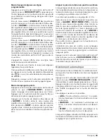
“CONT/UNIT UNLEVEL”
(continue/measuring tool
out of levelling range) is indicated on the display. The
rotation is stopped and the laser flashes in point oper-
ation. The current operating mode is stored.
After the shock-warning function has actuated, press
the right selection button
4
above
“CONT”
(continue).
The shock-warning function is restarted and the meas-
uring tool starts the levelling. As soon as the measuring
tool is levelled in, it starts in the stored operating mode.
Now, check the height of the laser beam with a refer-
ence point and correct the height, if required.
The shock-warning function can also be set in such a
manner that it is not automatically switched on when
switching on the measuring tool. Switching on the
function at a later point of time is of course possible.
To change the standard setting of the shock-warning
function when switching on the measuring tool, pro-
ceed as follows:
With the measuring tool switched off, press and hold
the right selection button
4
while switching the meas-
uring tool on.
Working with Automatic Levelling (“ON”)
After switching on, the measuring tool checks the hor-
izontal and vertical position, and automatically com-
pensates irregularities within the self-levelling range of
±
5°.
When the measuring tool is inclined by more than 5°
after switching on or after a position change, levelling
is no longer possible. The rotor is stopped and the
laser is switched off. If the grade alongside the Y-axis
is too steep,
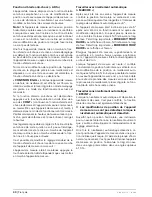
“ERROR/Y TOO STEEP”
is indicated
on the display. If the grade alongside the X-axis is too
steep,
“ERROR/X TOO STEEP”
is indicated on the
display.
In this case, switch the measuring tool off, re-align it
and switch the measuring tool on again. If the measur-
ing tool is not re-positioned, it is automatically switched
off after 2 minutes.
When the measuring tool is levelled in, it continuously
checks the horizontal and vertical position. Automatic
re-levelling takes place after position changes. If the
measuring tool cannot be re-levelled after 3 seconds,
the rotor is stopped during the levelling procedure to
avoid faulty measurements, and the laser flashes. The
shock-warning function remains active.
OBJ_BUCH-971-001.book Page 25 Wednesday, August 12, 2009 8:46 AM
Summary of Contents for AL-Series
Page 2: ...2 2 610 A15 112 12 8 09 6 5 3 4 3 8 7 2 2 1 9 12 13 16 17 18 14 15 11 10 13 ALGR...
Page 3: ...3 2 610 A15 112 12 8 09 19 21 22 23 24 20 25 B A...
Page 4: ...4 2 610 A15 112 12 8 09 28 27 26 29 30 31 32 33 34 35 37 36 38 39 40 RC400X...
Page 155: ...E 155 2 610 A15 112 12 8 09 f f 10 f f 2 IEC 60825 1 f f UV f f f f f f f CST berger 23 f 23...
Page 158: ...158 E 2 610 A15 112 12 8 09 f f f 163 24 f f ON OFF 6 9 1 5 162 0 00 30 s 5 161 60 s ON OFF 6...
Page 163: ...E 163 2 610 A15 112 12 8 09 30 s 12 20 m 100 m 20 m 20 m Service Bosch 30 m 30 m 0 00 I 30 m...
Page 165: ...E 165 2 610 A15 112 12 8 09 5 8 13 13 5 8 B 24 5 8 13 24 24 15 cm 23 23 23 1 9...
Page 240: ...240 2 610 A15 112 12 8 09 f f 10 f f 2 IEC 60825 1 f f f f f f f f f CST berger 23 f 23...
Page 243: ...243 2 610 A15 112 12 8 09 f f f 248 24 f f 6 9 1 5 247 0 00 30 5 245 60 6...
Page 255: ...255 2 610 A15 112 12 8 09 Bosch 10 oe e e e oe e e e 251 252...
Page 256: ...256 2 610 A15 112 12 8 09 f f 10 f f 2 IEC 60825 1 f f f f f f f f f CST berger 23 f 23...
Page 270: ...270 2 610 A15 112 12 8 09 Bosch 10 C a a c ep i i i C a a c ep i i i 267 267...
Page 285: ...285 2 610 A15 112 12 8 09 f f 10 f f 2 IEC 60825 1 f f f f f f f f f CST berger 23 f 23...
Page 294: ...294 2 610 A15 112 12 8 09 22 600 min 1 25 3 25 297 5 8 13 13 24 5 8 13 24 24 15 cm 23 23 23...

