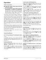
32
| English
2 610 A15 112 • 12.8.09
Operation
Initial Operation
f
Protect the remote control against moisture
and direct sunlight.
f
Do not subject the remote control to extreme
temperatures or variations in temperature.
As an example, do not leave it in vehicles for longer
periods. In case of large variations in temperature,
allow the remote control to adjust to the ambient
temperature before putting it into operation.
The remote control remains ready for operation as
long as batteries with sufficient voltage are inserted.
Set up the rotational laser in such a manner that the
signals of the remote control directly reach one of the
receiption lenses on the rotational laser (for this, see
the operating instructions of the rotational laser).
When the remote control cannot be pointed directly
against a receiption lens, the working range is
reduced. By reflecting the signal (e.g. against walls),
the working range can be improved, even for indirect
signals.
After pressing a button on the remote control, the illu-
minated operation indicator
27
indicates that a signal
was sent out. When the signal has reached the rota-
tional laser level, the rotational laser level emits an
audio signal for confirmation.
Switching the rotational laser on/off with the remote
control is not possible.
Operating Modes
The automatic levelling and the shock-warning func-
tion can not be switched on and off with the remote
control.
For detailed information of the rotational laser level
functions, see the operating instructions of the rota-
tional laser level (see “Rotational Laser Level”, from
page 20 on).
Rotational Operation
Press function-mode button
38
and then press the
“UP” 29
or
“DOWN” 36
button to start rotational
operation.
Press the
“UP ”
button
29
to increase the rotational
speed indicated on the display of the rotational laser
level or the
“DOWN”
button
36
to decrease the rota-
tional speed.
Line Operation with Standard Line
Press function-mode button
38
and then press the
“LONG” 40
or
“SHORT”
button
30
to start line oper-
ation with a standard line.
Press the
“LONG”
button
40
to increase the aperture
angle of the laser line or the
“SHORT”
button
30
to
decrease the aperture angle.
Press the
“CCW”
button
37
to rotate the laser line
counterclockwise within the the rotational plane or the
“CW”
button
32
to rotate the laser line clockwise.
Line Operation with Programmable Line
Press function-mode button
38
and then press the
“P TO P”
button
28
to start line operation with a pro-
grammable line.
Rotate the laser point at the desired left end point of
the laser line by pressing the
“CCW”
button
37
or the
“CW”
button
32
. Press the
“P TO P”
button
28
to
store the left end point.
Then rotate the laser point at the desired right end
point of the laser line by pressing the
“CCW”
button
37
or the
“CW”
button
32
. Press the
“P TO P”
button
28
to store the right end point.
The measuring tool now indicates a laser line between
both positioned points.
Point Operation
Press function-mode button
38
and then press the
“CCW”
button
37
or the
“CW”
button
32
to start
point operation.
Rotate the laser point to the desired position within
the rotational plane by pressing the
“CCW”
button
37
or the
“CW”
button
32
.
Grade Setting in the Horizontal Position
Press function-mode button
38
and then press the
“LEFT” 39
or
“RIGHT” 31
direction and grade but-
ton to access the grade menu.
Press the
“LEFT” 39
or
“RIGHT” 31
direction and
grade button to change the grade of the X-axis. Press
the
“UP” 29
or
“DOWN” 36
grade button to change
the grade of the Y-axis.
Aligning the Rotational Plane in the Vertical
Position
When the measuring tool is in the vertical position, the
rotational plane can be rotated around the Y-axis by
pressing the
“LEFT” 39
or
“RIGHT” 31
direction and
grade button (depends on whether the measuring tool
is in rotation, line or point operation).
OBJ_BUCH-971-001.book Page 32 Wednesday, August 12, 2009 8:46 AM
Summary of Contents for AL-Series
Page 2: ...2 2 610 A15 112 12 8 09 6 5 3 4 3 8 7 2 2 1 9 12 13 16 17 18 14 15 11 10 13 ALGR...
Page 3: ...3 2 610 A15 112 12 8 09 19 21 22 23 24 20 25 B A...
Page 4: ...4 2 610 A15 112 12 8 09 28 27 26 29 30 31 32 33 34 35 37 36 38 39 40 RC400X...
Page 155: ...E 155 2 610 A15 112 12 8 09 f f 10 f f 2 IEC 60825 1 f f UV f f f f f f f CST berger 23 f 23...
Page 158: ...158 E 2 610 A15 112 12 8 09 f f f 163 24 f f ON OFF 6 9 1 5 162 0 00 30 s 5 161 60 s ON OFF 6...
Page 163: ...E 163 2 610 A15 112 12 8 09 30 s 12 20 m 100 m 20 m 20 m Service Bosch 30 m 30 m 0 00 I 30 m...
Page 165: ...E 165 2 610 A15 112 12 8 09 5 8 13 13 5 8 B 24 5 8 13 24 24 15 cm 23 23 23 1 9...
Page 240: ...240 2 610 A15 112 12 8 09 f f 10 f f 2 IEC 60825 1 f f f f f f f f f CST berger 23 f 23...
Page 243: ...243 2 610 A15 112 12 8 09 f f f 248 24 f f 6 9 1 5 247 0 00 30 5 245 60 6...
Page 255: ...255 2 610 A15 112 12 8 09 Bosch 10 oe e e e oe e e e 251 252...
Page 256: ...256 2 610 A15 112 12 8 09 f f 10 f f 2 IEC 60825 1 f f f f f f f f f CST berger 23 f 23...
Page 270: ...270 2 610 A15 112 12 8 09 Bosch 10 C a a c ep i i i C a a c ep i i i 267 267...
Page 285: ...285 2 610 A15 112 12 8 09 f f 10 f f 2 IEC 60825 1 f f f f f f f f f CST berger 23 f 23...
Page 294: ...294 2 610 A15 112 12 8 09 22 600 min 1 25 3 25 297 5 8 13 13 24 5 8 13 24 24 15 cm 23 23 23...

