INSTRUCTION MANUAL Digital Light Engraver
6
Operation and Cleaning
Effective date
30.09.2013
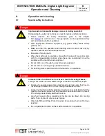
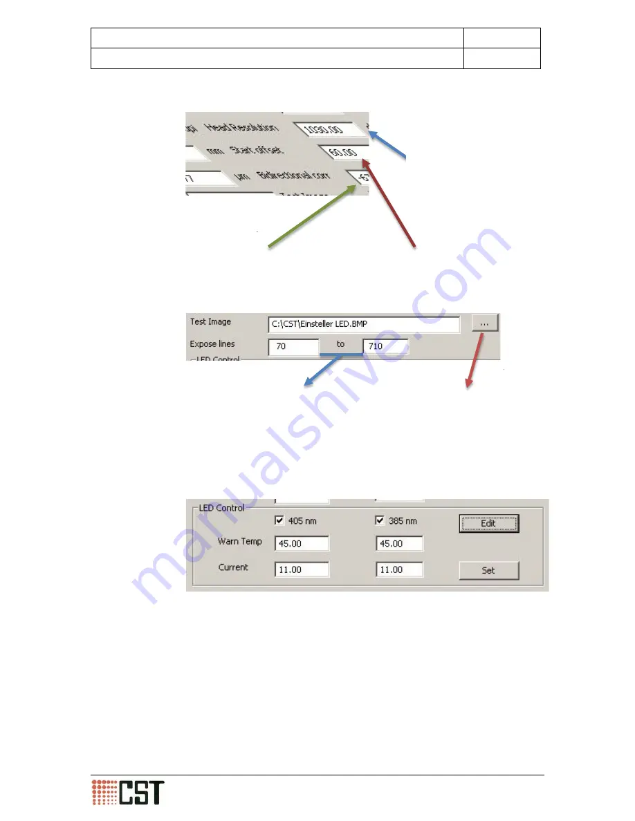
The following screen shot shows the possible LED power settings as well
as the temperature limit settings for the LEDs. In order to be able to acti-
vate this function, please contact CST for the required password.
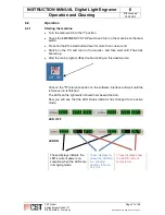
In the example above, both LEDs are supplied with 11 amps.
The temperature limit is set to 45°C. When the temperature limit is ex-
ceeded, the temperature is displayed in
red
. If this is the case, the opera-
tor must check the LED cooling system immediately.
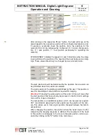
The “Test Image” field shows the path to
the test image file which is used to pro-
ject a still image
The ”Expose lines“ settings determine the maximum value
of the lines during the imaging. These value are set by the
service technician during installation and should not be
changed by the user.
The “Start offset” value sets a deviation for the
head in the Y direction at the start of the imag-
ing. The optimum value is set by the service
technician.
The “Bidirectional corr“ value sets the correction
value in the system so that, when the bidirectional
imaging mode is being used, the starting opera-
tion is set correctly.
The ”Head Resolution” value
sets the resolution of the sys-
tem during the imaging. This
value depends upon the
lenses in use. The value is de-
termined by the service tech-
nician by testing and must
never be changed. Changing
the values could result in the
imaging being incorrect or
even banding.
CST GmbH
Königsberger Straße 117
47809 Krefeld - Germany
Page 47 of 69
Betriebsanleitung DLE-AF 01.0 engl.docx


