background image

Table of Contents

PowerStation RS Monitor User Guide

iii

Calibrating the Touchscreen. . . . . . . . . . . . . . . . . . . . . . . . . . . . . . . . . . . . . . . .  46

Calibrating under MS-DOS  . . . . . . . . . . . . . . . . . . . . . . . . . . . . . . . . . . . . .  47

Calibrating under Windows 95, 98, or NT  . . . . . . . . . . . . . . . . . . . . . . . . . .  48

Adjusting the Video Image . . . . . . . . . . . . . . . . . . . . . . . . . . . . . . . . . . . . . . . . .  49

Chapter 5 Maintaining and Troubleshooting 

the RS Monitor . . . . . . . . . . . . . . . . . . . . . . . . . . . . . . . . .  53

Cleaning the Screen . . . . . . . . . . . . . . . . . . . . . . . . . . . . . . . . . . . . . . 54

Recalibrating the Touchscreen . . . . . . . . . . . . . . . . . . . . . . . . . . . . . . 54

Performing Internal Maintenance . . . . . . . . . . . . . . . . . . . . . . . . . . . . 54

Electrostatic Discharge (ESD) Precautions  . . . . . . . . . . . . . . . . . . . . . . . . . . . .  55

Opening and Closing the Back Cover. . . . . . . . . . . . . . . . . . . . . . . . . . . . . . . . .  55

Opening the back cover . . . . . . . . . . . . . . . . . . . . . . . . . . . . . . . . . . . . . . . .  55

Closing the back cover . . . . . . . . . . . . . . . . . . . . . . . . . . . . . . . . . . . . . . . . . 56

Replacing a Fuse . . . . . . . . . . . . . . . . . . . . . . . . . . . . . . . . . . . . . . . . . . . . . . . .  57

Replacing the Backlight Bulbs  . . . . . . . . . . . . . . . . . . . . . . . . . . . . . . . . . . . . . .  58

Resolving Common Problems  . . . . . . . . . . . . . . . . . . . . . . . . . . . . . . 62

Problems with Display Operation . . . . . . . . . . . . . . . . . . . . . . . . . . . . . . . . . . . .  63

Computer is on, the video cable is connected, but the screen is blank . . . .  63

"Unsupported video mode" message appears . . . . . . . . . . . . . . . . . . . . . . .  63

The touchscreen does not work properly, 

or calibration seems incorrect (touchscreen monitors only)  . . . . . . . . .  63

After calibrating the touchscreen, it does not work

or follow your finger (touchscreen monitors only)  . . . . . . . . . . . . . . . . .  64

Problems with the Displayed Image . . . . . . . . . . . . . . . . . . . . . . . . . . . . . . . . . .  64

Image does not fill the screen  . . . . . . . . . . . . . . . . . . . . . . . . . . . . . . . . . . .  64

Image extends beyond the screen . . . . . . . . . . . . . . . . . . . . . . . . . . . . . . . .  65

Characters shimmer or appear fuzzy . . . . . . . . . . . . . . . . . . . . . . . . . . . . . .  65

When video mode is changed, the screen image shifts left or right . . . . . . .  65

When video mode is changed, the screen image shifts up or down  . . . . . .  66

Summary of Contents for POWERSTATION RS

Page 1: ...POWERSTATION RS MONITOR PowerStation RS Monitor User Guide ...

Page 2: ......

Page 3: ...CTC Parker Automation Phone 513 831 2340 50 W TechneCenter Drive Milford Ohio 45150 Technical Support 513 248 1714 A3 05728 101 POWERSTATION RS MONITOR User Guide ...

Page 4: ...dards However should a problem occur with your hardware or with the software protection key CTC s standard product warranty covers these items for 15 months from the date of shipment from CTC Exceptions appear below PowerStation RS backlight bulbs have a 90 day warranty Push button lamps are not covered under warranty Third party products carry the manufacturer s specified warranty For all display...

Page 5: ...ntation Standards 5 ISO Symbols 5 Customer Support Services 6 Product Technical Support 6 Technical Support Products 7 Product Support Program 7 Chapter 2 Introducing the PowerStation RS Monitor 9 Specifications 10 Physical Specifications 10 Display Specifications 10 Video Modes Supported 11 Environmental Specifications 11 Electrical Specifications 12 Testing Specifications 12 Chemical Resistance ...

Page 6: ... the Monitor 23 Chapter 4 Connecting the RS Monitor to a Computer 25 Connecting to a Computer 26 Connecting to the PowerStation RS PC 26 Connecting to Other Computers 27 Starting Up 28 Setting Up the RS Monitor 30 Setting the Monitor Type 30 Installing the Touchscreen Drivers and Utilities 33 Installing the touchscreen driver and utilities under MS DOS 33 Installing the touchscreen driver and util...

Page 7: ...7 Replacing the Backlight Bulbs 58 Resolving Common Problems 62 Problems with Display Operation 63 Computer is on the video cable is connected but the screen is blank 63 Unsupported video mode message appears 63 The touchscreen does not work properly or calibration seems incorrect touchscreen monitors only 63 After calibrating the touchscreen it does not work or follow your finger touchscreen moni...

Page 8: ...nds appear in the image 66 Image appears faded or washed out 66 Top or bottom half of the screen looks dark 66 Appendix A RS Monitor Dimensional Drawings 67 12 1 Monitor Back View 67 12 1 Monitor Side View 68 15 1 Monitor Back View 69 15 1 Monitor Side View 70 Index 71 ...

Page 9: ...ble arm It can be used with the PowerStation RS PC or with other computers that run MS DOS or Windows 95 98 or NT operating systems This manual describes the RS Monitor s features and technical specifications It also explains procedures for installing main taining and troubleshooting the monitor Please take time to review the manual and all related documentation before operating the unit Chapter C...

Page 10: ...ts an overview of this manual the other documentation provided with the RS Monitor and CTC s customer support services Chapter 2 Introducing the PowerStation RS Monitor Describes the monitor s specifications and the ports available to connect the monitor to a computer and a power source Chapter 3 Installing the RS Monitor Explains how to mount the monitor in an enclosure Chapter 4 Connecting the R...

Page 11: ...out the RS Monitor and describes how to install configure and maintain the unit Please read this manual in its entirety before installing or operating the monitor Software Components The PowerStation RS Monitor is shipped with the following disks included in the package These disks contain various utilities and files you may occasionally need Touchscreen Software Disks These disks are shipped only...

Page 12: ...tion on product updates and service bulletins 3 Back up the CTC software that came with the monitor using Windows Explorer or the MS DOS diskcopy command 4 Read any Release Notes enclosed with the monitor This document provides important information about the RS Monitor that does not appear in this manual Install the RS Monitor Once you have unpacked the monitor and completed the steps listed abov...

Page 13: ...ins information that you should pay particular attention to while reading Follow this informa tion to save time and or minimize problems Warning Contains information on safety issues Fol low this information to prevent equipment damage or per sonal injury ISO Symbols This symbol is the International Standards Organization ISO symbol for Caution ISO 3864 No B 3 1 This symbol denotes information tha...

Page 14: ...ts The Product Support Program PSP Product Technical Support The Product Technical Support department welcomes any ques tion that might arise as you develop or run your applications We offer complimentary support for any customer whether you are an end user original equipment manufacturer OEM system inte grator or distributor If you have a question about the PowerStation RS Monitor be sure to comp...

Page 15: ...rom the ground up by writing custom communica tions drivers or by designing special modules to perform functions unique to your application Our team of specialists is flexible so they can create a project development schedule that meets your needs You can contact the PCS Coordinator by phone at 1 800 233 3329 or by email at pcs ctcusa com Product Support Program The Product Support Program is desi...

Page 16: ...Customer Support Services Chapter 1 Manual Overview and Support Services 8 PowerStation RS Monitor User Guide ...

Page 17: ...r that can be used with the PowerStation RS PC or with another computer running MS DOS or Windows 95 98 or NT It comes in 12 1 SVGA and 15 1 XGA display sizes This chapter outlines the monitor s specifications and describes its available connectors Chapter Contents Specifications 10 Available Connectors 14 ...

Page 18: ...mensions H x W x D 12 1 Monitor 12 1 x 15 1 x 3 6 307 59mm x 382 52mm x 91 44mm 15 1 Monitor 13 3 x 16 8 x 3 8 337 82mm x 426 72mm x 96 14mm I O Ports Video Input Analog RGB through a standard 15 pin DSUB connector Touchscreen input Serial RS232 DCE through a standard 9 pin DSUB connector Weight 12 1 Monitor 14 6 lbs 6 6Kg 15 1 Monitor 16 5 lbs 7 4Kg estimated Category Specifications 12 1 Monitor ...

Page 19: ...X 480 60 Hz 31 47 Khz 640 X 480 72 Hz 37 86 Khz 640 X 480 75 Hz 37 50 Khz 640 X 480 85 Hz 43 27 Khz 800 X 600 56 Hz 35 16 Khz 800 X 600 60 Hz 37 88 Khz 800 X 600 72 Hz 48 08 Khz 800 X 600 75 Hz 46 87 Khz 800 X 600 85 Hz 53 67 Khz 1024 X 768 60 Hz 48 36 Khz 1024 X 768 70 Hz 56 48 Khz 1024 X 768 75 Hz 60 02 Khz Category Specifications Operating temperature 32o 122o F 0o 50o C Storage temperature 13o...

Page 20: ... accord ingly However always use reliable sources of power and isolate all communication cables from power lines to enhance noise immunity If possible locate the monitor away from machinery that produces intense electrical noise for example arc welders Otherwise isolate the input power to the monitor from the equipment generating the noise Testing Specifications The RS Monitor conforms to the test...

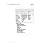
Page 21: ...hol ethyl methyl Automatic transmission fluid Warning Sustained exposure to brake fluid or Gunk brand degreaser can cause damage to monitor materials Screen Chemical Resistance Acetone Sulfuric Acid 10 Motor oil MEK Hydrochloric Acid 10 Gasoline Toluene Acetic Acid Machine oil Methylene Chloride Phosphoric Acid Salad oil Isopropyl Alcohol Sodium Hydroxide 10 Silicone Xylene Carbon Tetrachloride Si...

Page 22: ...t used only in touchscreen monitors Analog Video Input port The following illustration shows a side view of the RS Monitor with its three connectors Touchscreen Cable Diagram For RS Monitors with a touchscreen the diagram below shows the connections between the monitor and a host computer RS 232 Communication 2400 Baud 24VDC Power Input port Touchscreen port Analog Video Input port Host Computer R...

Page 23: ...Station RS Monitor User Guide 15 Video Input Signals The table below shows the video inputs from a host computer to the RS Monitor Video Cable Signals 1 Red 6 Green Shield 11 N C 2 Green 7 Blue Shield 12 N C 3 Blue 8 GND 13 HSYNC 4 N C 9 N C 14 VSYNC 5 Red Shield 10 GND 15 N C ...

Page 24: ...Available Connectors Chapter 2 Introducing the PowerStation RS Monitor 16 PowerStation RS Monitor User Guide ...

Page 25: ...tor and mount the monitor in an enclosure You will need to read the latter two sections of this chapter Creating a Cutout and Mounting the Monitor in an Enclosure only if you intend to mount the RS Monitor in an enclosure If you are mounting the monitor on an adjustable arm see the documen tation that accompanies the arm for installation instructions Chapter Contents Selecting a Location 18 Creati...

Page 26: ...or must be mounted in an enclosure that meets a NEMA 4 rating 3 If you purchased an RS Monitor with mounting cover the monitor must use a limited energy power source such as CTC s External AC Power Supply Adapter P1X PWRAC Class I Division 2 Guidelines If you purchased a Class I Division 2 compliant monitor you must always follow these guidelines to maintain a safe operating environment 1 Suitable...

Page 27: ... sure that your power source is completely compatible with the monitor before starting the unit Temperature Humidity Guidelines You can safely operate the RS Monitor within the temperature range specified in Environmental Specifications on page 11 of this manual However if the monitor is mounted in an enclosure remember that the temperature within the enclosure is generally higher than the externa...

Page 28: ... Cutout dimensions for the RS 12 1 and 15 1 monitors are shown in the table below See RS Monitor Dimensional Drawings on page 67 of this manual for more detailed information about your monitor s dimensions Important An External AC Adapter for the RS Monitor is available from CTC and can be mounted on the back of all RS Moni tors that do not have a mounting cover If you choose to mount the adapter ...

Page 29: ...C is available from CTC along with an installation kit that will enable you to mount the adapter either on the back of the monitor or near the monitor The adapter can only be mounted on the back of RS Monitors that do not have a mounting cover Important If you intend to mount the External AC Adapter on the back of the RS Monitor be sure to take the adapter s dimensions into account when planning t...

Page 30: ...e Notice that the lower mounting clamp has a special exten sion that reaches down over the AC connection and holds it in place 4 Fasten the adapter to the monitor with the four retaining screws included in the adapter installation kit The completed installation should look like the illustration below Note For instructions on how to mount the External AC Adapter near the monitor see the documentati...

Page 31: ...bottom of the monitor and one on each side The prongs at the bottom of each clamp should face backward and should hook into the slots in each space The end of each screw should point toward the front of the enclosure 3 Tighten each screw against the front of the enclosure to a torque of 0 5 lb in After you have mounted the RS Monitor you are ready to connect the monitor to a computer start up your...

Page 32: ...Mounting the Monitor in an Enclosure Chapter 3 Installing the RS Monitor 24 PowerStation RS Monitor User Guide ...

Page 33: ...rSta tion Remote System will be set up and ready for you to use once you connect the components However if you connect your monitor to another computer you will have to perform some monitor setup procedures This chapter will tell you how to connect the RS Monitor to your computer how to prepare the monitor to work with your computer and how to read and adjust the on screen display OSD Chapter Cont...

Page 34: ...ou connect them The connections are simple and are described below Connecting to the PowerStation RS PC To connect your RS Monitor to the PowerStation RS PC complete the following steps Connect the 15 pin video cable to the Analog Video Input port on both the monitor and the PC If you have a touchscreen monitor connect the 9 pin touch screen cable to the Touchscreen port on the monitor and the COM...

Page 35: ...C running MS DOS or Windows complete the following steps Connect the 15 pin video cable to the Analog Video Input port at the left side of the monitor and to the 15 pin video port on your computer If you have a touchscreen monitor connect the 9 pin touch screen cable to the Touchscreen port on the monitor and the 9 pin serial port on your computer that you will use for touchscreen communications ...

Page 36: ... permanently connected equipment a readily accessi ble disconnect device should be incorporated in the fixed wir ing For pluggable equipment the socket outlet should be installed near the equipment and should be easily accessible Special Note concerning use in EU member countries Proper installation of the RS Monitor for use in European Union countries requires the use of a harmonized power cord T...

Page 37: ...r and to the voltage source see the preceding illustration Warning Voltage input to the unit should be within the range speci fied in Electrical Specifications on page 12 of this manual 4 Connect the ground stud at the lower left side of the monitor to an effective known earth ground see the preceding illus tration 5 Connect your computer to a power source 6 Turn on the monitor Power On Off switch...

Page 38: ...ivities will depend upon the operating system your computer uses and whether your monitor has a touchscreen or not The setup activities and the components for which you would perform them are shown in the table below A discussion of each activity follows the table Setting the Monitor Type You will only have to set the monitor type if your computer is running a Windows operating system Important Wi...

Page 39: ...C the screen displayed as you set the monitor type may differ slightly from the one shown below 4 In the Settings dialog box click the button at the lower right that says either Change Display Type or Advanced Properties Either a Change Display Type or Advanced Display Proper ties dialog box will appear 5 If a Change Display Type dialog box appears on your screen click the Change button under the ...

Page 40: ...splay Type or the Monitor dialog box the Select Device dialog box will appear as shown below Make sure that Show All Devices at the lower left is selected 9 In the Manufacturers list box select Standard Monitor Types 10 In the Models list box select the type of RS Monitor you are using either Super VGA 800 X 600 12 1 monitor Super VGA 1024 X 768 15 1 monitor 11 Click OK A message will appear telli...

Page 41: ...n computers running MS DOS or Windows 95 98 or NT If you are operating your monitor under MS DOS read the instructions beginning immediately below If you are operating your monitor under Windows 95 98 or NT read the instructions that begin on page 36 Important If you need additional instructions for installing or unin stalling any of the touchscreen software see the README TXT files on your touchs...

Page 42: ...he touchscreen controller to be connected to and press Return Note The COM2 port on the PowerStation RS PC is configured by default for communication with the RS touchscreen monitor 6 The installation process will begin At the end of the process the system will check three files and it will ask if you want to continue to each procedure a The system will analyze your TOUCH INI file to de termine wh...

Page 43: ...hould not need to change them If you are installing the touchscreen drivers on a system running CTC s Interact software you will need to manually add the NOBOUNDS option to the AUTOEXEC BAT file To do this follow these steps 1 Use your DOS text editing program for example MS DOS Edit to access the AUTOEXEC BAT file 2 Find the entry that loads the touchscreen driver The entry is C TOUCH DOX SC3DOX ...

Page 44: ...iately below with the name of the appropriate subdirec tory appearing where the bracketed expression is C subdirectory mouse Note If the mouse driver entry doesn t appear before the touch screen driver you will have to type the entry yourself Do not use brackets when you type the entry After you type the entry save it exit the DOS editing program and restart your computer Crtl Alt Del Installing t...

Page 45: ...g and you must have a floppy disk drive connected 1 From the Start menu click Settings and Control Panel The Control Panel window will appear as shown below 2 In the Control Panel window click the Add New Hard ware icon The Add New Hardware Wizard dialog box will appear 3 In the Add New Hardware Wizard dialog box click Next 4 In the next dialog box you will be asked if you want Windows to search f...

Page 46: ...acturer and model of your new hardware Do not select a manufacturer or model Instead select Have Disk in the lower right part of the dialog box 7 The Install from Disk dialog box will open as shown on the next page Insert your DynaPro SC3 Touchscreen Driver for Windows 95 diskette KA 72816 or your DynaPro SC3 Touchscreen Driver for Windows NT diskette KA 72817 into the floppy disk drive ...

Page 47: ...Add New Hardware Wizard will display the touch screen driver file as shown below Make sure that DynaPro Thin Film SC3 Touch Screen Driver is selected and click Next 11 In the next dialog box you will be told that Windows can install your touchscreen software Click Finish to complete the installation 12 When the installation is complete close all dialog boxes and windows on the desktop 13 From the ...

Page 48: ...er Windows NT 4 00 the following files will be placed on the hard drive where your Windows NT directory resides WINNT40 Directory File TOUCH W9X readme txt default ini touchcfg exe touchcfg help mbswap exe mbswap hlp touchini exe touchwerr exe touchosi dll uninstal exe uninstal inf insx32 dll insx16 dll msvcrt40 dll xnmhn458 dll xnmba458 dll xnmte458 dll WINDOWS SYSTEM vsc3d vxd Directory File TOU...

Page 49: ...be one that is detectable by Windows 95 or 98 such as a Microsoft or Logitech mouse Also an appropriate driver must be installed for your mouse To install an appropriate mouse driver follow these steps 1 Connect your mouse to the computer 2 From the Windows Start menu click Settings and Control Panel The Control Panel window will open 3 In the Control Panel Window click the Add New Hard ware icon ...

Page 50: ...en and mouse should operate concurrently Windows NT 4 00 To operate a mouse and touchscreen concurrently under Windows 4 00 use the following procedure to install a mouse driver 1 Connect your mouse to the computer 2 From the Windows Start menu click Settings and Control Panel The Control Panel window will open 3 Click the Mouse icon in the Control Panel window The Mouse Properties dialog box will...

Page 51: ...elect Device dialog box will appear as shown below It will display a list of pointer devices compatible with any mouse you have connected to your computer 6 In the Select Device dialog box select the type of mouse you are using 7 Click OK 8 From the Windows Start menu click Shut Down and Restart the Computer 9 After you restart the computer your touchscreen and mouse should operate concurrently ...

Page 52: ...tion data will be saved on the host computer follow these steps 1 At the DOS prompt for example A type TOUCHCFG EXE You will be asked to choose from a list of activities you want to perform Type I for Interface 2 At the next menu change the Calibration Data setting to read Host Type N to do this 3 Type O for OK 4 Leave Connection set to UART 5 Press ESC to return to the DOS prompt Changing calibra...

Page 53: ...Utilities dialog box click Interface The Interface Configuration Options dialog box will appear as shown below 3 In the Interface Configuration Options dialog box under Connection select UART 4 Under Cal Data select Controller 5 Click OK 6 Close all open dialog boxes 7 From the Windows Start menu click Shut Down and Restart the Computer ...

Page 54: ...tch the list above and download them To download new settings you must first change the Connection setting under Interface to UART and restart the computer If you attempt to download the new settings while Connection is set to RS232 the controller will cease communication until the computer is restarted Calibrating the Touchscreen You will need to calibrate the touchscreen only if you have a touch...

Page 55: ...alibration When the next screen appears you will be calibrating video mode 80 x 25 Text 2 3 4 Type C again for Calibrate 5 Place your finger on the square on the screen and hold until you hear a beep Follow the instructions on the screen by touching each square as it appears there will be three squares altogether 6 Type V to select a new video mode 7 Type 0 for the 640 x 480 16 color Graphics mode...

Page 56: ...ties folder Note The Touchscreen Utilities will be pre installed in the PowerStation RS PC They can be installed on other systems by using the touchscreen driver installation diskettes shipped with your RS Monitor See the procedure for Installing the Touchscreen Drivers and Utilities on page 33 3 Click the Configuration icon from the Touchscreen Utilities folder The Configuration Utilities dialog ...

Page 57: ...n the target and follow the instructions on the screen 7 Click Exit when you are finished Adjusting the Video Image The PowerStation RS Monitor is equipped with an on screen display OSD that allows you to adjust the video image for the best possible picture You can do this whether you have a touch screen or non touchscreen monitor You can make these adjust ments by using the four buttons at the lo...

Page 58: ...unctions like an arrow key on a keyboard enabling you to reverse through the OSD icons in order to select the setting you want to adjust Once you have selected a setting this button enables you to decrease the value of the adjustment you want to make When you press the On Off button you will see the following icons in the on screen display Brightness Adjusts the backlight level in order to increas...

Page 59: ...round Switches the OSD background on or off when you press the Select button Default Settings Loads the factory default video settings when you press the Select button To adjust the video image on your monitor follow these steps 1 Press the On Off button to display the OSD 2 Use the buttons to choose the icon for the adjustment you want to make 3 Press the Select button to activate the adjustment ...

Page 60: ...ff in 25 seconds Some of the video adjustments you can make are global and affect all video modes while others affect picture quality only for the video mode in use You may need to make the latter adjustments whenever you change the video resolution or refresh rate The following table shows which adjustments are global and which are unique for the video mode in use Adjustment Nature of Value Brigh...

Page 61: ...y you will need to perform routine mainte nance on some of the monitor s components This chapter provides instructions on cleaning the monitor screen recalibrating the touchscreen performing internal maintenance on the monitor and resolving common problems in operation Chapter Contents Cleaning the Screen 54 Recalibrating the Touchscreen 54 Performing Internal Maintenance 54 Resolving Common Probl...

Page 62: ...r with touchscreen your touchscreen was calibrated by CTC before your monitor was shipped However you may need to recalibrate the touchscreen when you begin using the RS Monitor for the first time when you connect the monitor to a new computer or whenever the cursor location and the place on the screen where the user touches do not match See Calibrating the Touchscreen on page 46 of this manual fo...

Page 63: ...of the monitor in an ESD safe location using appropriate grounding methods Wear an ESD wrist strap connected to an effective known earth ground Always ground yourself to remove any static charge be fore you touch the video controller board inside the mon itor s back cover Be particularly careful not to touch the components on the video controller board Keep any monitor part in its anti static pack...

Page 64: ...nd protected against static discharge 7 If your monitor has been mounted on an adjustable arm remove the screws that attach the monitor mounting cover to the back cover of the monitor remove the monitor mounting cover 8 Remove the two retaining screws that secure the back cover as shown below 9 Open the back cover from the right side It will swing from right to left on its hinges 10 Proceed to the...

Page 65: ...Reconnect the monitor to a power source 6 Turn on the monitor and computer Replacing a Fuse The RS Monitor uses a 3 15A fuse IEC 127 2 sheet 1 fast acting type which may need to be replaced To replace the fuse follow these steps Warning Be sure to observe ESD precautions while working inside the RS Monitor 1 Open the back cover of the monitor see the procedure for Opening the back cover on page 55...

Page 66: ...tor see the procedure for Opening the back cover on page 55 of this manual 2 Disconnect the three internal cables as shown below a Lift up the locking clamps from either side of the monitor data cable connector at the right side of the monitor frame disconnect the cable b Disconnect the backlight cable from its connection on the video controller board inside the back cover c If the monitor has a t...

Page 67: ... Tilt the frame up on its right side so that you can see the ends of the backlight bulbs facing up as shown below Note If you are right handed you may be able to perform this procedure more easily if you turn the frame as shown below so that the bulbs are to your right 7 Pull the ends of the cable leading from each bulb through the hole in the back of the frame near it so that the cables are on th...

Page 68: ...l flat tipped screwdriver gently pull back the white tab next to the top of each bulb and lift the bulb out of the frame as shown in the next two illustrations You can most easily remove a bulb by gently pulling up on its cable Backlight bulb cable Holes for retracting backlight bulb cables Pull back backlight bulb tab Pull up backlight bulb ...

Page 69: ...t the lower left side of the frame outside in 12 Fasten the frame in place with the 10 screws removed in step 4 13 Replace the back cover of the monitor onto its hinges 14 Re attach the backlight cable and if necessary the internal touchscreen cable to their connections on the video controller board 15 Re attach the monitor cable to its connection at the right side of the frame Gently push down on...

Page 70: ... Product Technical Support department at 513 248 1714 Use the table below to find discussions of specific problems The problems are divided into two categories 1 Problems with display operation 2 Problems with the displayed image Problems with Display Operation Page Computer is on the video cable is connected but the screen is blank 63 Unsupported video mode message appears 63 The touchscreen does...

Page 71: ... 57 of this manual Important If the monitor is exposed to a power supply voltage over 51VDC its built in protection will blow the fuse In this case you must correct the cause of the over voltage Unsupported video mode message appears 1 The currently chosen video mode is not in the monitor s list of supported modes Consult the chart of Video Modes Supported on page 11 of this manual and set up your...

Page 72: ...n may be damaged Contact CTC Product Technical Support at 513 248 1714 about having the touch screen replaced 4 Cables or wiring inside the monitor may be damaged Open the back cover of the monitor see the procedure for Opening the back cover on page 55 of this manual and inspect for broken loose or frayed cables or wiring Secure loose cables and replace damaged cables or wiring Problems with the ...

Page 73: ...al Size adjustment to fit the image completely on the screen Important This problem may occur if the horizontal size is mis adjusted by as little as one pixel too few or too many so try to make as precise an adjustment as possible 3 The current vertical refresh rate may not be optimal If your computer s video card and driver will support it change the vertical refresh rate until you find one that ...

Page 74: ...correct Use the OSD Phase Control adjustment to sharpen the image 2 The horizontal size is not correct for the current video mode Use the OSD Horizontal Size adjustment to fit the image completely on the screen Important This problem may occur if the horizontal size is mis adjusted by as little as one pixel too few or too many so try to make the adjustment as precise as possible 3 The current vert...

Page 75: ...PowerStation RS Monitor User Guide 67 RS Monitor Dimensional Drawings 12 1 Monitor Back View 15 1 382 524mm 14 1 358 14mm 3 4 86 36mm 10 0 254 00mm 5 12 70mm Appendix A ...

Page 76: ...onitor User Guide Appendix A RS Monitor Dimensional Drawings 12 1 Monitor Side View 11 1 281 94mm 1 6 40 64mm 1 8 45 72mm 2 9 73 66mm 2 50 63 5mm 4 7 119 38mm 7 2 182 88mm 9 2 233 68mm 12 1 307 34mm 1 1 27 94mm 75 19 05mm ...

Page 77: ...PowerStation RS Monitor User Guide 69 Appendix A RS Monitor Dimensional Drawings 15 1 Monitor Back View 10 0 254mm 15 8 401 32mm 16 8 426 72mm 5 0 127 00mm 5 12 70mm ...

Page 78: ...Monitor User Guide Appendix A RS Monitor Dimensional Drawings 15 1 Monitor Side View 1 6 40 64mm 2 50 63 5mm 4 7 119 38mm 7 2 182 88mm 9 2 233 68mm 13 3 337 82mm 11 1 281 94mm 1 0 25 40mm 2 0 50 80mm 3 0 26 7mm 75 19 05mm ...

Page 79: ...or 23 Interact 7 35 41 63 ISO symbols 5 L location selecting a location 18 19 M MachineLogic 7 maintenance 54 61 cleaning the screen 54 opening the back cover 55 performing internal maintenance 54 57 recalibrating the touchscreen 54 replacing a fuse 57 replacing backlight bulbs 58 61 N NEMA 11 12 18 O on screen display OSD 49 52 64 65 66 P PowerStation RS Monitor adjusting the video image 49 52 ba...

Page 80: ... specifications 10 testing specifications 12 video modes supported 11 T Technical Support Products 7 temperature humidity guidelines 19 touchscreen 30 54 63 64 cable diagram 14 calibrating 46 49 drivers and utilities 3 installing touchscreen drivers and util ities 33 43 operating a mouse and touchscreen concurrently 36 41 43 port 14 26 27 storing calibration data 44 46 Touchscreen Software Disks 3...

Reviews: