Chapter 2 Installation
16
2.2.1 Cable connectors
Front
All IO cable connections are located on front panel of IO line cards. Cables of each card extend from the front panel
connectors. Please reserve enough space in the front of the chassis to extend these cables.
Back
Located on the rear of the chassis are the alarm terminals relay contacts, that connect to rack alarm circuits. Under failure
conditions, alarm signals are sent from the shelves/racks.
* SNMP Port
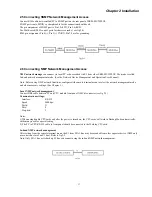
interface provides a 10/100Base-TX twisted pair Ethernet interface. (under development)
* G.703 ext. clock
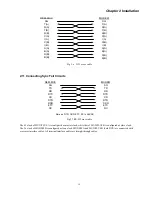
interface provides two types of interfaces, balanced (RJ-45) and unbalanced (BNC) connectors.
* RS-485 interface:
for connecting expansion chassis control signals via RJ-45 x 2 connectors.
* HDB 62 interface:
for connecting the expansion chassis bus.
2.3 Auxiliary Connections on Rear of Chassis
Fig 2.3 ERM-MUX/PLUS Backplane (2 x AC POWER shown)
2.4 Connecting Power Supplies
User can select 110VAC, 220VAC or DC power modules. AC and DC backplane are different. AC+AC model is shown
in figure 2.3.
The connecter for alarm relays can be connected to the existing alarm system. When the Major Alarm (such as power
failure) or Minor Alarm (such as fans failure) occurs, the alarm relays can conduct signal to the whole alarm system.
Alarm Connectors Definition
:
Major Alarm and Minor Alarm.
Relay Connectors Definition
:
COM = common, NO = normally open, and NC = normally closed.
alarm
E1 modules
normal
alarm
Major
Alarm
CPU modules
normal
alarm
Power modules
normal
alarm
fan alarm
normal
alarm
I/O modules
normal
Ext clock port Signal Loss
Minor
Alarm
G703 Ext clock
Ext clock port Signal Normal
Table 2.1 Major Alarm and Minor Alarm content.
Summary of Contents for ERM-MUX
Page 1: ...ERM MUX Plus E1 Multi Service Access Multiplexer ...
Page 2: ......
Page 8: ...Table of Contents ...
Page 20: ...Chapter 2 Installation 20 This page was left blank intentionally ...
Page 30: ...Chapter 3 LED Indicators and Cable Pin Definitions 30 This page was left blank intentionally ...
Page 58: ...Chapter 8 Application Notes 58 This page was left blank intentionally ...
Page 59: ......
Page 60: ......


