Chapter 2 Installation
18
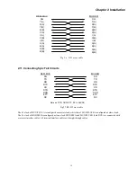
REM-MUX
MODEM
SG
TD(A)
RD(A)
RTS
CD
ETC(B)
RC(B)
SG
TD(A)
RD(A)
RTS
CD
ETC(A)
RC(A)
TD(B)
RD(B)
TD(B)
RD(B)
ETC(A)
RC(A)
ETC(B)
RC(B)
2.7 Connecting Monitor/Control Terminal
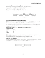
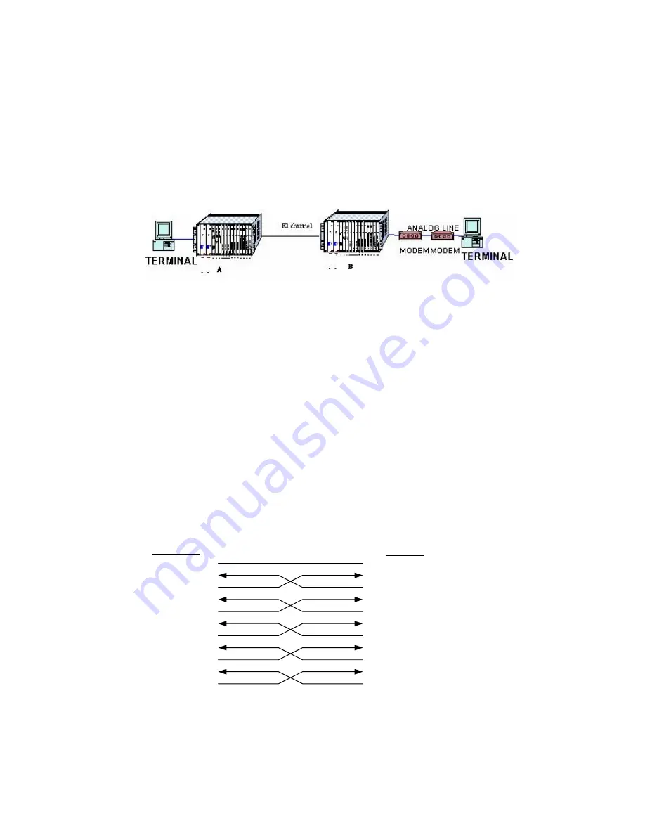
Connect a DB9 to DB9 cable between the PC COM port and CPU card's front panel LOC Ctrl connecter.
Connect a crossover or null-modem DB9 to DB9 cable between the modem and CPU card's front panel LOC Ctrl connector.
Communication settings:
Interface: RS-232
Speed:
9600bps/
Parity:
N
Bits:
8
Stop bits:
1
Fig. 2.6 Local and remote management terminal connections
2.8 Connecting G.703 External Clock
Unbalance BNC connecter on backplane (EXT CLK)
Balanced RJ-45 connecter on backplane (EXT CLK), Pin assignments: Pin 4,5 Receive, 7,8 Ground.
2.9 Connecting E1 Circuits
Connect a DB37 to Unbalance (75ohm) BNC or Balanced (120ohm) RJ-45 connecters cable to the DB37 provided on the front
panel of the E1 card.
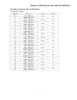
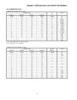
The RJ-45 follows USOC RJ-48C standard: Pin1,2 Receive, 4,5 Send, 7,8 Ground.
Note:
1) When using E1 Backup mode, the E1 cable can randomly connect to either E1A or E1B card on the front panel.
2) When using a single E1, use the E1A slot card.
2.10 Connecting I/O Cards
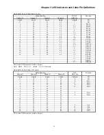
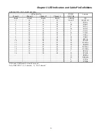
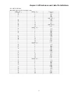
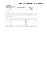
For details of all the different IO cards and their connections from front panel with different cables, see chapter 3.
The IO cards all have DCE interface. To emulate DTE you must use crossover cables. For DTE crossed cable connection
methods see fig 2.5 fig 2.9 fig 2.6.
Fig2.5 V.35 cross cable
Summary of Contents for ERM-MUX
Page 1: ...ERM MUX Plus E1 Multi Service Access Multiplexer ...
Page 2: ......
Page 8: ...Table of Contents ...
Page 20: ...Chapter 2 Installation 20 This page was left blank intentionally ...
Page 30: ...Chapter 3 LED Indicators and Cable Pin Definitions 30 This page was left blank intentionally ...
Page 58: ...Chapter 8 Application Notes 58 This page was left blank intentionally ...
Page 59: ......
Page 60: ......


