Chapter 2 Installation
19
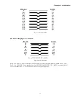
REM-MUX
MODEM
SG
T(A)
R(A)
C(A)
I(A)
S(A)
B(A)
SG
T(A)
R(A)
C(A)
I(A)
S(A)
B(A)
T(B)
R(B)
T(B)
R(B)
S(B)
B(B)
S(B)
B(B)
C(B)
I(B)
C(B)
I(B)
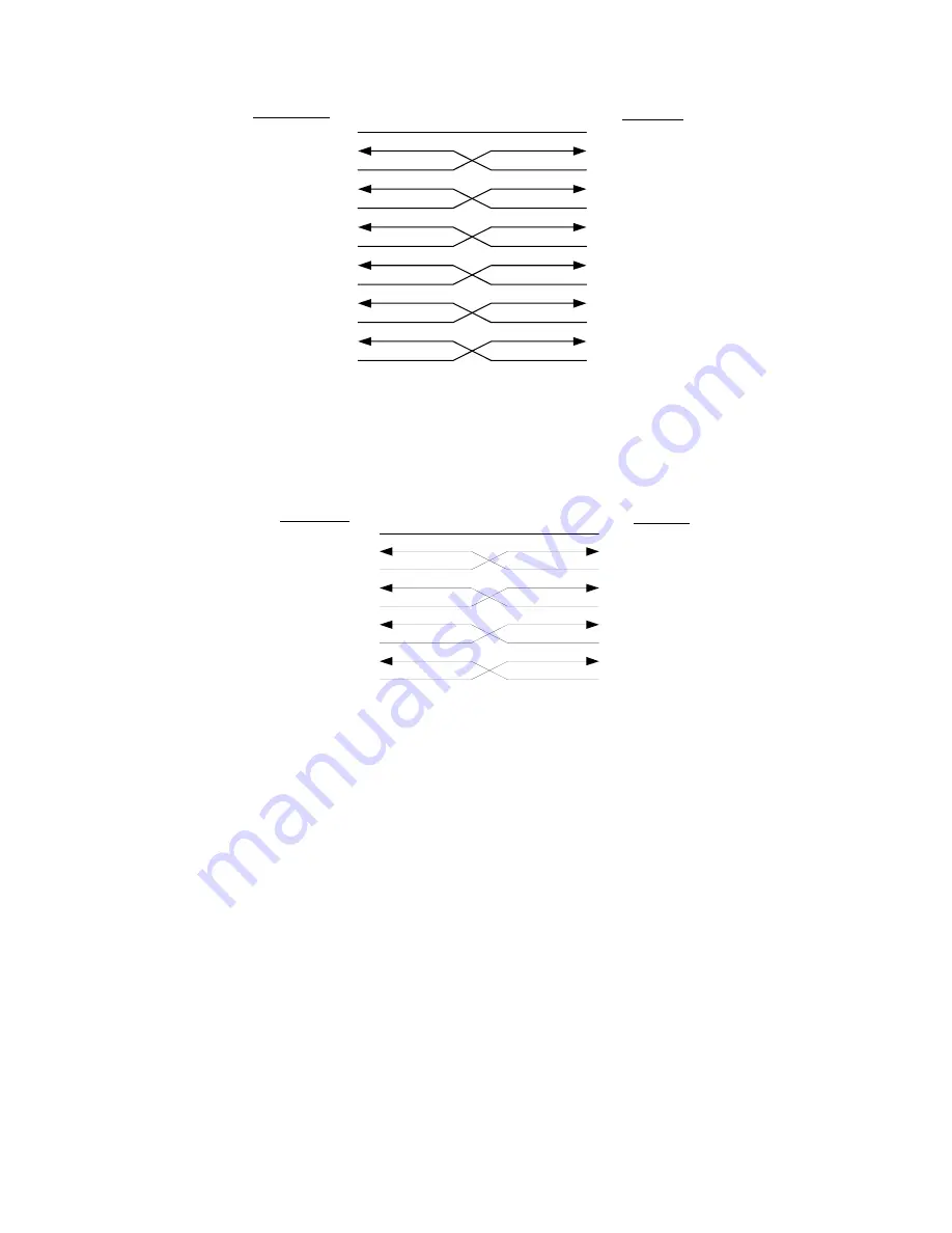
Fig 2.6 X.21 cross cable
2.11 Connecting Sync Tail Circuits
Fig 2.7 RS-232 cross cable
The E1 clock of MUX/PLUS A is configured as master clock, while that of MUX/PLUS B is configured as slave clock.
The Tx clock of MODEM B is configured as loop clock. MODEM A and MUX/PLUS B (both DCE) are connected with
crossover interface cables. All terminal interface cables are straight through cables.
REM-MUX
MODEM
SG
TD
RD
RTS
CD
DTR
DSR
ETC
RC
SG
TD
RD
RTS
CD
DTR
DSR
ETC
RC
Note:no DTR、DSR、ETC、RC in ASYNC
Summary of Contents for ERM-MUX
Page 1: ...ERM MUX Plus E1 Multi Service Access Multiplexer ...
Page 2: ......
Page 8: ...Table of Contents ...
Page 20: ...Chapter 2 Installation 20 This page was left blank intentionally ...
Page 30: ...Chapter 3 LED Indicators and Cable Pin Definitions 30 This page was left blank intentionally ...
Page 58: ...Chapter 8 Application Notes 58 This page was left blank intentionally ...
Page 59: ......
Page 60: ......


