Chapter 3 LED Indicators and Cable Pin Definitions
21
Chapter 3 LED Indicators and Cable Pin Definitions
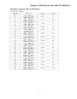
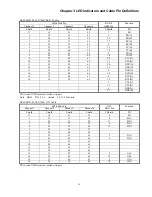
3.1 Front panel LED indicators
LED names
Color
Descriptions
POWER Card
green
when lit indicates power is normal, when off - power failure
CPU Card:
PWR
Major Alarm
Minor Alarm
Failure
Active
Link
green
red
red
red
green
yellow
when lit indicates Card power normal, when off - Card power fault
when lit indicates major alarm
when lit indicates minor alarm
when lit indicates configuration failure. when off - normal
when lit indicates working. when off -standby
when lit indicates SNMP PORT LINK, when off - NO LINK
E1 card:
PWR
Alarm
Active
Ch1 SYNC Signal
Loss Loss
Ch2 SYNC Signal
Loss Loss
Ch3 SYNC Signal
Loss Loss
Ch4 SYNC Signal
Loss Loss
Ch5 SYNC Signal
Loss Loss
Ch6 SYNC Signal
Loss Loss
Ch7 SYNC Signal
Loss Loss
Ch8 SYNC Signal
Loss Loss
green
red
green
red red
red red
red red
red red
red red
red red
red red
red red
when lit indicates Card power normal, when off - Card power fault
when lit indicates Card alarm, when off - normal
when lit indicates working, when off -standby
when lit indicates SYNC Loss/ Signal Loss, when off - normal
when lit indicates SYNC Loss/ Signal Loss, when off - normal
when lit indicates SYNC Loss/ Signal Loss, when off - normal
when lit indicates SYNC Loss/ Signal Loss, when off - normal
when lit indicates SYNC Loss/ Signal Loss, when off - normal
when lit indicates SYNC Loss/ Signal Loss, when off - normal
when lit indicates SYNC Loss/ Signal Loss, when off - normal
when lit indicates SYNC Loss/ Signal Loss, when off - normal
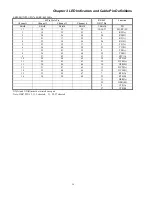
G703/64K Card:
PWR
Alarm
Ch1
Ch2
Ch3
Ch4
green
red
red
red
red
red
when lit indicates Card power normal, when off - Card power fault
when lit indicates Card alarm, when off - normal
when lit indicates Signal Loss, when off - normal (CH1)
when lit indicates Signal Loss, when off - normal (CH2)
when lit indicates Signal Loss, when off - normal (CH3)
when lit indicates Signal Loss, when off - normal (CH4)
N64K Card
(
V.35
and RS232
)
:
PWR
Alarm
Ch1 RD TD
Ch2 RD TD
Ch3 RD TD
Ch4 RD TD
green
red
green green
green green
green green
green green
when lit indicates Card power normal, when off - Card power fault
when lit indicates Card alarm, when off – normal
lit when data is transmitted/ received
lit when data is transmitted/ received
lit when data is transmitted/ received
lit when data is transmitted/ received
A/SYNC 128 Card:
PWR
Alarm
Ch1 RD TD
Ch2 RD TD
Ch3 RD TD
Ch4 RD TD
Ch5 RD TD
Ch6 RD TD
green
red
green green
green green
green green
green green
green green
green green
when lit indicates Card power normal, when off - Card power fault
when lit indicates Card alarm, when off – normal
lit when data is transmitted/ received
lit when data is transmitted/ received
lit when data is transmitted/ received
lit when data is transmitted/ received
lit when data is transmitted/ received
lit when data is transmitted/ received
Summary of Contents for ERM-MUX
Page 1: ...ERM MUX Plus E1 Multi Service Access Multiplexer ...
Page 2: ......
Page 8: ...Table of Contents ...
Page 20: ...Chapter 2 Installation 20 This page was left blank intentionally ...
Page 30: ...Chapter 3 LED Indicators and Cable Pin Definitions 30 This page was left blank intentionally ...
Page 58: ...Chapter 8 Application Notes 58 This page was left blank intentionally ...
Page 59: ......
Page 60: ......


