Chapter 3 LED Indicators and Cable Pin Definitions
26
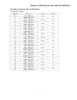
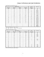
ERM-MUX-PLUS N*64K RS-449 Cable
68Pin Male Pin
Channel 1
Channel 2
Channel 3
Channel 4
RS-449
DB37 Pin
Function
Shield Shield Shield Shield 1,Shield PG
17 18 51 52
19-20-37
SG-RC-SC
1 19 35 53 6 RD(A)
2 20 36 54 24
RD(B)
3 21 37 55 8 RC(A)
4 22 38 56 26
RC(B)
5 23 39 57 5 TC(A)
6 24 40 58 23 TC(B)
7 25 41 59 4 TD(A)
8 26 42 60 22
TD(B)
9 27 43 61 17
ETC(A)
10 28 44 62 35
ETC(B)
11 29 45 63 12
DTR(A)
12 30 46 64 30
DTR(B)
13 31 47 65 13
DCD(A)
14 32 48 66 31
DCD(B)
15 33 49 67 7
RTS(A)
16 34 50 68 25
RTS(B)
11
DSR(A)
29
DSR(B))
9
CTS(A)
27
CTS(B)
XX(A) and XX(B) must be twisted wire pair.
Note: DB37 PIN:13, 11, 9
shorted. 31, 29, 27
shorted
Summary of Contents for ERM-MUX
Page 1: ...ERM MUX Plus E1 Multi Service Access Multiplexer ...
Page 2: ......
Page 8: ...Table of Contents ...
Page 20: ...Chapter 2 Installation 20 This page was left blank intentionally ...
Page 30: ...Chapter 3 LED Indicators and Cable Pin Definitions 30 This page was left blank intentionally ...
Page 58: ...Chapter 8 Application Notes 58 This page was left blank intentionally ...
Page 59: ......
Page 60: ......


