Chapter 3 LED Indicators and Cable Pin Definitions
28
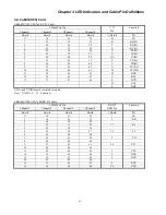
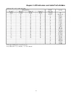
ERM-MUX/PLUS A/SYNC 128 RS232 Cable (cont.)
HDB62
(
M
)
DB25/F
(
5
)
56 2
TD
36 3
RD
15 4
RTS
17 5
CTS
6
DSR
18 7
GND
58 8
CD
16 15
TC
57 17
RC
38 20
DTR
37 24
ETC
DB25/F
(
6
)
59 2
TD
19 3
RD
39 4
RTS
41 5
CTS
6
DSR
42 7
GND
61 8
CD
40 15
TC
60 17
RC
21 20
DTR
20 24
ETC
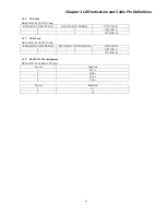
3.2.4 G703/64K Card
ERM-MUX/PLUS G703/64K Cable
RJ-45 Function
1 RTIP
2 RRING
3 TTIP
4 TRING
7 GND
8 GND
3.2.5 E&M Card
ERM-MUX/PLUS E&M Cable
RJ-45 Definition
1
4W (send) /2W LINE A
2
4W (send) /2W LINE B
3
4W (receive) /2W LINE A
4
4W (receive) /2W LINE B
5 E-LINE(Signaling)
6 M-LINE(Signaling)
7 SG
8 SB
Summary of Contents for ERM-MUX
Page 1: ...ERM MUX Plus E1 Multi Service Access Multiplexer ...
Page 2: ......
Page 8: ...Table of Contents ...
Page 20: ...Chapter 2 Installation 20 This page was left blank intentionally ...
Page 30: ...Chapter 3 LED Indicators and Cable Pin Definitions 30 This page was left blank intentionally ...
Page 58: ...Chapter 8 Application Notes 58 This page was left blank intentionally ...
Page 59: ......
Page 60: ......


