Chapter 3 LED Indicators and Cable Pin Definitions
29
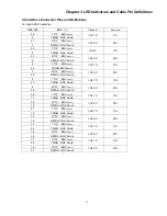
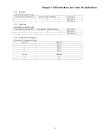
3.2.6 FXS Card
ERM-MUX-PLUS FXS Cable
RJ45(LINK TO MUXPLUS)
RJ11(LINK TO PHONE)
FUNCTION
4 2
2W
LINE-A
5 3
2W
LINE-B
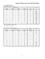
3.2.7 FXO Card
ERM-MUX-PLUS FXO Cable
RJ45(LINK TO MUXPLUS)
RJ11(LINK TO EXCHANGE)
FUNCTION
4 2
2W
LINE-A
5 3
2W
LINE-B
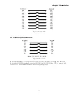
3.2.8 RS485/422 Pin Assignment
ERM-MUX-PLUSRS485/422 Port
4 wires
Function
1 RX(+)
2 RX(-)
3 TX(+)
4 TX(-)
2 wires
Function
1 (+)
2 (-)
Summary of Contents for ERM-MUX
Page 1: ...ERM MUX Plus E1 Multi Service Access Multiplexer ...
Page 2: ......
Page 8: ...Table of Contents ...
Page 20: ...Chapter 2 Installation 20 This page was left blank intentionally ...
Page 30: ...Chapter 3 LED Indicators and Cable Pin Definitions 30 This page was left blank intentionally ...
Page 58: ...Chapter 8 Application Notes 58 This page was left blank intentionally ...
Page 59: ......
Page 60: ......


