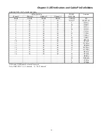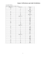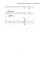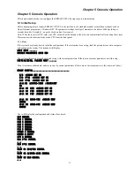
Chapter 4 Hardware Settings
32
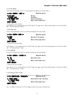
4.3 E&M Card
4.3.1 E&M Type Setting
See Fig4-1: 2W is 2 Wire mode , 4W is 4 Wire mode
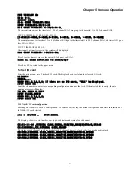
4.3.2 Signaling Type Setting
For the Audio , E&M-V4 card can be supported no signaling , the LEDs are condition of the data .
When no signaling , in fig4-1 , the J6 should be shorted.
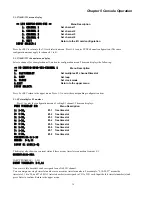
4.3.3 E&M Signaling Type Setting
Table 4-1 A means connected to A side, B means connected to B side, C means not connected
。
Jumper
setting
Jumper
TYPE 1 TYPE 2 TYPE 3 TYPE 4 TYPE 5
S1 B
B
B
A
A
S2 C
A
A
B
C
S3
A
B
A
B
A
S4 B
B
B
A
A
S5 B
B
B
A
A
Table 4-1
:
5 kind of Signaling Type S1-S5 setting
1SA1
1SA5
2W
4W
2SA1
2SA5
3SA1
3SA5
CH1
CH2
CH3
A
CH4
CH2
CH3
CH1
RJ45X6
SSA1-SSA
3
4SA1
4SA5
CH4
CH5
CH6
Pin 1
Fig 4-2 E&M card
Pin 8
CH1
CH2
CH3
CH4
CH5
CH6
top
bottom
5SA1
5SA5
CH5
6SA1
6SA5
CH6
A
A
A
A
A
B
B
B
B
B
B
J6
Fig 4-1 E&M Card Jumpers setting
2W
4W
SSB1-SSB3
2W
4W
SSC1-SSC3
2W
4W
SSD1-SSD3
2W
4W
SSE1-SSE3
2W
4W
SSF1-SSF3
Summary of Contents for ERM-MUX
Page 1: ...ERM MUX Plus E1 Multi Service Access Multiplexer ...
Page 2: ......
Page 8: ...Table of Contents ...
Page 20: ...Chapter 2 Installation 20 This page was left blank intentionally ...
Page 30: ...Chapter 3 LED Indicators and Cable Pin Definitions 30 This page was left blank intentionally ...
Page 58: ...Chapter 8 Application Notes 58 This page was left blank intentionally ...
Page 59: ......
Page 60: ......


