Chapter 5 Console Operation
34
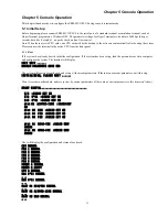
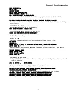
SLOT 04 FXO NORMAL
… …
SLOT 05 G703-64K NORMAL
… …
SLOT 06 FXS NORMAL
The configuration and status of other cards will be seen later in this chapter. Press ESC or enter at the menu.
At this point, the console monitors the status of each card and displays the status of configuration changed on the terminal.
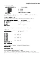
E1A 8*E1 LINE 1 SIGNAL LOSS
E1A 8*E1 LINE 2 SYNC LOSS
E1A 8*E1 LINE 3 SIGNAL LOSS
E1A 8*E1 LINE 4 SIGNAL LOSS
E1A 8*E1 LINE 5 SIGNAL LOSS
E1A 8*E1 LINE 6 SIGNAL LOSS
E1A 8*E1 LINE 7 SIGNAL LOSS
E1A 8*E1 LINE 8 SIGNAL LOSS
E1B 8*E1 LINE 1 SIGNAL LOSS
E1B 8*E1 LINE 2 SIGNAL LOSS
E1B 8*E1 LINE 3 SIGNAL LOSS
E1B 8*E1 LINE 4 SIGNAL LOSS
E1B 8*E1 LINE 5 SIGNAL LOSS
E1B 8*E1 LINE 6 SIGNAL LOSS
E1B 8*E1 LINE 7 SIGNAL LOSS
E1B 8*E1 LINE 8 SIGNAL LOSS
CONNECT TO NET MANAGER...
EXIT FROM NET MANAGER.
5.1.2 Input Password
Under console monitor, operations such as modifying parameters can be done only after inputting password at the prompt.
The system displays:
PLEASE INPUT PASSWORD:
The password must be six-characters and can contain any letter or number. You can try again if the wrong password is input.
The default factory password is '111111' (no quotes). The system will show * for each character input. Press "ESC" key will
escape from input. With the correct password keyed in, you may start with menu configuration.
5.1.3 Main Menu
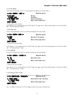
<< MAIN MENU >>
Menu Description
1
.
E1 CONFIG
Browse and modify E1 card parameters
2
.
I/O CONFIG
Browse and modify I/0 card parameters
3
.
DISPLAY CONFIG
Display configuration parameters
4
.
CONFIG
Configure and save
5
.
SAVE DEFAULT
Set the device as default
6
.
SET SYSTEM
Browse and modify system parameters
7
.
BERT
Bit Error Rate Test
0
.
EXIT
Exit menu to monitor mode
INPUT SELECT:
Press number key 1 to 7 to enter corresponding menu.
Or press 0 or ESC to return to the monitor mode.
Summary of Contents for ERM-MUX
Page 1: ...ERM MUX Plus E1 Multi Service Access Multiplexer ...
Page 2: ......
Page 8: ...Table of Contents ...
Page 20: ...Chapter 2 Installation 20 This page was left blank intentionally ...
Page 30: ...Chapter 3 LED Indicators and Cable Pin Definitions 30 This page was left blank intentionally ...
Page 58: ...Chapter 8 Application Notes 58 This page was left blank intentionally ...
Page 59: ......
Page 60: ......


