Chapter 5 Console Operation
38
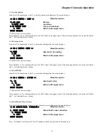
5.3.2 N64K/V35 menu display
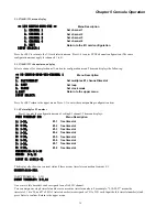
<< I/O CONFIG-N64K-V35 >>
Menu Description
1. CHANNEL 1
Set channel 1
2. CHANNEL 2
Set channel 2
3. CHANNEL 3
Set channel 3
4. CHANNEL 4
Set channel 4
0. EXIT
Return to the I/O card configuration
INPUT SELECT:1
Press 0 or ESC to return to the I/O card selection menu. Press 1-4 to enter SYNC channel configuration. (The same
configuration menus apply for channels 1 to 4).
5.3.3 N64K/V35 channel menu display
Select a channel, for example channel 1, and enter configuration menu. The menu displays the following:
<< IO CONFIG-N64K-V35-CHANNEL 1
>>
Menu Description
1.
E1/TIMESLOT
Set multiplex E1 channel/timeslot
2.
LOOP
Set loop
3.
CLOCK
Set clock mode
0.EXIT
Return to the upper menu
INPUT SELECT:
Press 0 or ESC return to the upper menu. Press 1-3 to enter the corresponding configuration item.
5.3.4 Set multiplex E1 number
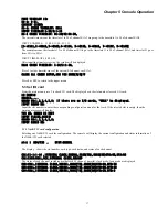
Press 1 to enter the configuration menu of setting E1 channel. The menu displays:
The display also shows any current status if there are any timeslots connection from any E1.
CURRENT:E1A1-NULL
INPUT EXAMPLE: 3-9,11
INPUT TIMESLOT: 3-9,11
One or more idle timeslots can be assigned to one N64 I/O channel:
You can assign one single timeslot number or consecutive timeslot numbers. For example, "5,10-20,27" means the
timeslots 5, 10 to 20, and 27 of E1A1 (selected earlier) are assigned to CH1 of I/O card. Input the idle timeslot number(s) and
press Enter to confirm. Return to the upper menu.
FREE TIMESLOT IS:
Menu Description
1: 1-31,
E1-1 free timeslot
2: 1-31,
E1-2 free timeslot
3: 1-31,
E1-3 free timeslot
4: 1-31,
E1-4 free timeslot
5: 1-31,
E1-5 free timeslot
6: 1-31,
E1-6 free timeslot
7: 1-31,
E1-7 free timeslot
8: 1-31,
E1-8 free timeslot
CURRENT:E1-1:1-10
USAGE: 3-9,11
INPUT E1 LINE(1-8)
Summary of Contents for ERM-MUX
Page 1: ...ERM MUX Plus E1 Multi Service Access Multiplexer ...
Page 2: ......
Page 8: ...Table of Contents ...
Page 20: ...Chapter 2 Installation 20 This page was left blank intentionally ...
Page 30: ...Chapter 3 LED Indicators and Cable Pin Definitions 30 This page was left blank intentionally ...
Page 58: ...Chapter 8 Application Notes 58 This page was left blank intentionally ...
Page 59: ......
Page 60: ......

