Chapter 5 Console Operation
42
5.8 Set FXO Card
Please refer to FXS configuration menu. The settings for FXO are the same, with the exception that there is no work mode
setting for the FXO cards. (Only FXS supports the 'hot line' function.).
5.9 Set E&M Card
When entering the E&M card configuration under the I/O card sub-menu, the system checks and displays the current
configuration and status information of the E&M card selected
slot 3 E&M STATE:NORMAL
Slot number card type card status
CH1:NOE1:NULL,NORMAL,1.5db,2.0db
The display shows the status of each channel, including multiplexed E1 channel, timeslot, clock mode, loop mode, TX LEVEL,
RX LEVEL
CH2:NOE1:NULL,NORMAL,0.0db,0.0db
CH3:NOE1:NULL,NORMAL,0.0db,0.0db
CH4:NOE1:NULL,NORMAL,0.0db,0.0db
CH5:NOE1:NULL,NORMAL,0.0db,0.0db
CH6:NOE1:NULL,NORMAL,0.0db,0.0db
5.9.1 E&M MENU DISPLAY
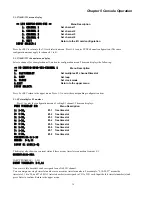
<< I/O CONFIG-E&M >>
Menu Description
1. CHANNEL 1
Set channel 1
2. CHANNEL 2
Set channel 2
3. CHANNEL 3
Set channel 3
4. CHANNEL 4
Set channel 4
5. CHANNEL 5
Set channel 5
6. CHANNEL 6
Set channel 1
0. EXIT
Return to the main menu of IO card
INPUT SELECT:
Press 0 or ESC to return to the I/O card sub-menu.
Press 1 to 6 to enter the E&M channel configuration. The setting procedure is the same for each channel, 1-6.
5.9.2 E&M Channel menu display
When selecting one E&M channel, for example CH1, the menu displays:
<< I/O CONFIG-E&M-CHANNEL 1 >>
Menu Description
1. E1/TIMESLOT
Set multiplex E1 channel
2. LOOP
3. TX LEVEL
4. RX LEVEL
0.EXIT
Return to the upper menu
INPUT SELECT:
Press 0 or ESC return to the upper menu. Press 1 or 2 to enter the corresponding configuration sub-menu. The subsequent
procedure is the same as N64K/V35 configuration. However, only one timeslot can be assigned to one channel.
Press 3 or 4 to enter the TX/RX level
Current Tx level:1.5db
INPUT DB(-20...+8):
Summary of Contents for ERM-MUX
Page 1: ...ERM MUX Plus E1 Multi Service Access Multiplexer ...
Page 2: ......
Page 8: ...Table of Contents ...
Page 20: ...Chapter 2 Installation 20 This page was left blank intentionally ...
Page 30: ...Chapter 3 LED Indicators and Cable Pin Definitions 30 This page was left blank intentionally ...
Page 58: ...Chapter 8 Application Notes 58 This page was left blank intentionally ...
Page 59: ......
Page 60: ......


