Chapter 5 Console Operation
48
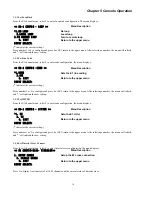
5.16.1 Display system version
Press 1 to enter the VERSION mode display menu
ERM-MUX-PLUS version 4.00
5.16.2 Modify System Clock
Press 2 to enter the CLOCK mode configuration menu. The menu will display:
<< SYSTEM CONFIG-CLOCK >>
Menu Description
1. INT OSC
Internal OSC is source
2. IO CLOCK
Set I/O as external clock
3. EXTERNAL CLOCK
Set external clock
*4. E1 RECOVER CLOCK [1]
E1A recover clock is source
0. EXIT
Return to the upper menu
INPUT SELECT:1
('*'indicates current setting.)
Press 1 to 4 to select the desired configuration, or press 0 or ESC to return to the upper menu. After configuration change by
pressing key 1 to 4, the system will refresh the menu, and '*' will indicate the new setting. If IO card is selected for clock
source, the system will check the I/O slots for presence of a compatible clock source cards.
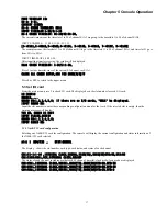
For example, the system might show:
IO CLOCK VAILD BOARD SLOT:
slot 01 N64K-V35
slot 05 G703
slot 10 N64K-232
CURRENT IO CLOCK SLOT:NULL
The listed cards are all candidates for providing clock source. If entering 5, the system will show:
INPUT SLOT NO:5
Note: Only the clock from the
first channel (CH1)
of the selected slot can be used to apply clock for the whole system when
the I/O card clock is used.
5.17 Modify NMP /SNMP Parameter
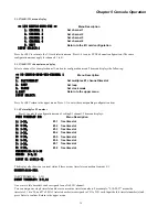
Please press 3 to enter "3.NMP CONFIG". The menu will display:
<< SYSTEM CONFIG-NMP >>
Menu Description
1. UP TIMESLOT
up timeslot of in-band NMP
2. DOWN TIMESLOT
down timeslot of in-band NMP
3. DISABLE NMP
Disable NMP
4. IP ADDRESS
Change IP address
5. DEVICE ADDRESS
Device address
6. DOWN DEVICE ADDRESS
Down device address of in-band NMP
0. EXIT
Return to the upper menu
INPUT SELECT:1
5.17.1 Set up timeslot of in-band NMP
Please press 1 to enter "1. UP TIMESLOT ". The menu will display:
CURRENT:E1-1:31
INPUT TIMESLOT(INPUT 0 TO CANCEL):31
5.17.2 Set down timeslot of in-band NMP
Please press 1 to enter "2. DOWN TIMESLOT ". The menu will display:
INPUT E1 LINE(1-8):2
FREE TIMESLOT IS:2: 1-31,
CURRENT:E1-2:NULL
INPUT TIMESLOT(INPUT 0 TO CANCEL):31
Summary of Contents for ERM-MUX
Page 1: ...ERM MUX Plus E1 Multi Service Access Multiplexer ...
Page 2: ......
Page 8: ...Table of Contents ...
Page 20: ...Chapter 2 Installation 20 This page was left blank intentionally ...
Page 30: ...Chapter 3 LED Indicators and Cable Pin Definitions 30 This page was left blank intentionally ...
Page 58: ...Chapter 8 Application Notes 58 This page was left blank intentionally ...
Page 59: ......
Page 60: ......


