Chapter 5 Console Operation
50
5.17.5 Device Address (NMP)
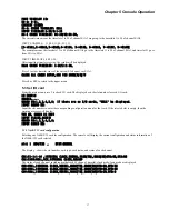
Please press 5 to enter "5. DEVICE ADDRESS " There are four address : ADDRESS 01, ADDRESS 02, ADDRESS 03 and
LEVEL. ADDRESS 01/02/03 is NMP address. For LEVEL input :
1.
If device directly connect to NMP system, then LEVEL input “0”
2.
If device connect to NMP system via another MUX-PLUS, then LEVEL input 1, 2, ……
CURRENT EQUIP ADDRESS:02,00,00,00
INPUT NEW EQUIP ADDRESS:
ADDRESS 01:2
ADDRESS 02:0
ADDRESS 03:0
LEVEL: 0
NEW EQUIP ADDRESS:02,00,00,00
5.17.6 SET DOWNDEVICE ADDRESS
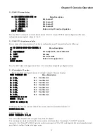
CURRENT DOWN DEVICE ADDRESS:2,0,0,1-2,0,0,11
INPUT 1st DOWN DEVICE ADDRESS:
ADDRESS 1:2
ADDRESS 2:0
ADDRESS 3:0
ADDRESS 5:1
INPUT 2nd DOWN DEVICE ADDRESS:
ADDRESS 1:2
ADDRESS 2:0
ADDRESS 3:0
ADDRESS 5:64
NEW DOWN DEVICE ADDRESS:2,0,0,1-2,0,0,64
5.18 SET BACKUP E1
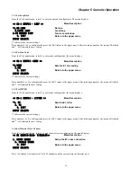
Please press 4 to enter "4. BACKUP E1 ". The menu will display:
<< SYSTEM CONFIG-BACKUP E1 >>
Menu Description
*1. DISABLE
2. ENABLE
0. EXIT
Return to the upper menu
INPUT SELECT:1
Press 0 or ESC return to the main menu. Press 1 or 2 to get system info and/or modify the configuration.
5.19 Set password
Please press 5 to enter "5. CHANGE PASSWORD ". The menu will display:
PLEASE INPUT PASSWORD:******
INPUT NEW PASSWORD(6 BYTES):******
INPUT NEW PASSWORD AGANI:******
5.20 SETUP TIME
Please press 6 to enter "6. SETUP TIME ". The menu will display:
CURRENT TIME: 03-09-11,16-31-30
TIME FORMAT: YY-MM-DD,HH-MM-SS
INPUT NEW TIME:
Summary of Contents for ERM-MUX
Page 1: ...ERM MUX Plus E1 Multi Service Access Multiplexer ...
Page 2: ......
Page 8: ...Table of Contents ...
Page 20: ...Chapter 2 Installation 20 This page was left blank intentionally ...
Page 30: ...Chapter 3 LED Indicators and Cable Pin Definitions 30 This page was left blank intentionally ...
Page 58: ...Chapter 8 Application Notes 58 This page was left blank intentionally ...
Page 59: ......
Page 60: ......


