Chapter 8 Application Notes
57
8.5 Implementation of multiplexing connection for voice/signaling
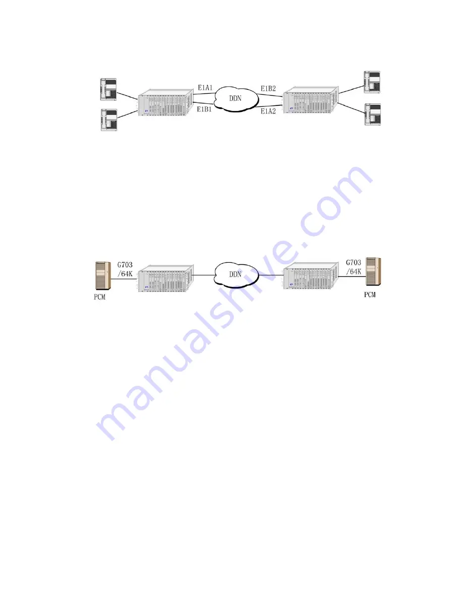
Fig. 8.5 Voice application
In the figure 8.5:
1. Connect telephone to ERM-MUX/PLUS via FXS card, and multiplex it to a time-slot of E1A1 and E1B1.
2. Connect the telephone of opposite side to ERM-MUX/PLUS via FXS card, and multiplex it to corresponding time-slot of
E1A2 and E1B2.
3. For E1 circuits of both sides, E1A1 is connected to E1B1, and E1B2 is connected to E1A2.
A makes communication with A*, and B makes communication with B*.
8.6 Typical application of G703-64K card
In the figure 8.6 Signal from G703-64K card is sent to opposite side via E1 line, and then sent to ERM-MUX/PLUS from the
opposite side by using E1 line. Users can be connected using ERM-MUX/PLUS.
Figure 8.6 G.703/64K Application
Summary of Contents for ERM-MUX
Page 1: ...ERM MUX Plus E1 Multi Service Access Multiplexer ...
Page 2: ......
Page 8: ...Table of Contents ...
Page 20: ...Chapter 2 Installation 20 This page was left blank intentionally ...
Page 30: ...Chapter 3 LED Indicators and Cable Pin Definitions 30 This page was left blank intentionally ...
Page 58: ...Chapter 8 Application Notes 58 This page was left blank intentionally ...
Page 59: ......
Page 60: ......


