FMUX03/V35
11
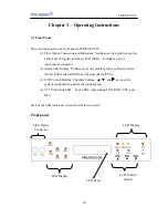
3-2 Rear Panel Control and LED Indicator Function
#
Control or
LED Indicator
Function
1 OLOS
LSR
Red light when there is a loss of in
Yellow light signals an alarm in Laser sending out energy
normally
2 TxD/RxD
CTS/RTS
Yellow light when received signal from remote unit
3 MAJ
Red light when there is a Major Alarm present
4 MIN
Yellow light when there is a Minor Alarm present
5 SYS
System normal or System failure
6 ALARM
Alarm Connector: D-Type 9 pin
7 ACO
Alarm Cut Off; Yellow light when the ACO button is
pressed to manually disable the audible alarm when a
problem occurs.
If any newer alarm is reported after the ACO button has
been pressed, the external alarm will activate again.
8 RST
Restart the system
9
▼
▲
These three buttons serve as the control and configure
buttons of FMUX03/V35
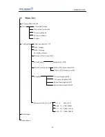
Summary of Contents for FMUX03/V35
Page 1: ......
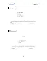
Page 17: ...FMUX03 V35 17 Main Menu Profile ...
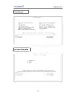
Page 18: ...FMUX03 V35 18 Configuration Alarm Status Report ...
Page 19: ...FMUX03 V35 19 Status Report Data port clock source ...
Page 20: ...FMUX03 V35 20 Data port clock invert Loopback ...
Page 21: ...FMUX03 V35 21 Data rate N 64K N 1 32 N 01 08 64K 512K ...
Page 22: ...FMUX03 V35 22 N 09 16 576K 1024K N 17 24 1088K 1536K ...


