background image

                                                                                    FMUX03/V35 


18


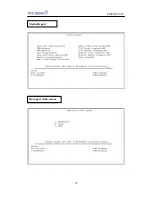
Configuration 

Alarm Status Report

Summary of Contents for FMUX03/V35

Page 1: ......

Page 2: ...t Connection 9 Chapter 3 Operating Instructions 10 3 1 Front Panel 10 3 2 Rear Panel Control and LED Indicator Function 11 3 3 Menu Tree 13 Chapter 4 Operating and Setup Instructions 14 4 1 Profile 14 4 2 System Configuration 15 4 3 Alarm Status Report 15 4 4 Craft Port Operation 15 4 5 How to Connect and setup the craft port 15 4 6 Operating From The Craft Port 16 Chapter 5 Loopback Test 24 5 1 G...

Page 3: ...friendly functions for monitoring maintaining and configuring the unit using LCD panel and VT 100 remote terminal access Its DC AC selectable power source insures a quality and reliable power supply CTC Union FMUX03 V35 provides the telecommunication industry a multipurpose and easy to use high quality fiber optics modem Operating from either AC or DC power module backup power supply is available ...

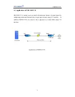
Page 4: ...used to extend the transmission distance of optical signal by multiplexing individual channels into a single optical stream using V 35 interface In addition FMUX03 V35 can connect a client equipment to a Central Office using V 35 interface Application of FMUX03 V35 ...

Page 5: ...50 Laser System Gain 20 30dB Fiber Type Single Mode 9 125um Optical Connector FC PC ST Alarm Detection and Indication Data port Interface TxD Transmit data DTE transmit data to DCE RxD Receive data DCE transmit data to DTE CTS Clear to send DCE to DTE RTS Request to send DTE to DCE Optical Interface LOS Loss of Signal The loss of optics signal Laser On Laser On indicator Alarm Indication Major ala...

Page 6: ...CD front panel to configure and monitor the system Craft port with DCE appearance Bits per second baud 9600bps Parity None Data Bits 8 bits Stop Bit 1 Power DC 36V 72VAC 90V 288V 57Hz 63Hz Physical Specifications FMUX03 V35 Dimensions Depth 220 mm Width 285 mm Height 44 5 mm Optical Link FC PC or ST Electrical Link DB 25 female connector Alarm Connector DB 9 connector Environment Operating Tempera...

Page 7: ... Dual OE Module 12dBm 1550D 1550 nm single mode loop reach up to 75km Dual OE Module 12dBm System Gain L Low power System Gain 16dB M Low power System Gain 20dB H Low power System Gain 25dB Power Module AC 1 Single 90 288 VAC power supply DC 1 Single 34 72 VDC power supply AC 2 Dual 90 264 VAC power supply DC 2 Dual 34 72 VDC power supply AC 1 DC 1 AC DC dual power supply Optical Connector F FC ty...

Page 8: ...t our nearest sales representative or our company directly if you suspect any damaged or missing parts Improper handling during shipment may cause early failure 2 3 Site Requirements The FCC requires telecommunication equipment to withstand electrical surge that may result from lighting strikes This equipment has been tested and found to comply with the FCC requirement Users should follow the prec...

Page 9: ...tlet To allow easy access to the equipment leave at least 36 inches 90 cm clearance in front and at least 4 inches 10 2 cm at the rear To avoid overheating leave at least 1 inch 2 5 cm on either side of FMUX03 V35 Also do not stack another equipment on top of FMUX03 V35 2 5 AC or DC Electrical Outlet Connection For safety and to prevent damage to FMUX03 V35 make sure that the power requirement mat...

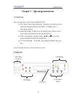
Page 10: ...f input output connector 2 Alarm LED Display Notifies users of a problem such as a Major Alarm MAJ Minor Alarm MIN and System Alarm SYS 3 LCD Control Buttons The three buttons and are used for system configuration and for the loopback test 4 V 35 Port Status LED Four LEDs representing TXD RXD CTS and RTS Each of the LED indicators is described below in detail Front panel Fiber Optics Connector LED...

Page 11: ...hen there is a Major Alarm present 4 MIN Yellow light when there is a Minor Alarm present 5 SYS System normal or System failure 6 ALARM Alarm Connector D Type 9 pin 7 ACO Alarm Cut Off Yellow light when the ACO button is pressed to manually disable the audible alarm when a problem occurs If any newer alarm is reported after the ACO button has been pressed the external alarm will activate again 8 R...

Page 12: ...minal port III Power Switch Controls On Off of the equipment IV There are 5 different power supply combinations with the SC AC dual module power supply AC only DC only dual AC dual DC AC DC redundancy Reference to Order Information V 35 Connector AC DC Power Power Switch Craft Alarm port ...

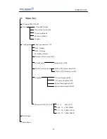
Page 13: ...rking 4 Switching Disable 5 Data port Flow Control OFF 6 Clock Source Internal Line DTE 7 Data Port Clock Invert DTE to DCE Clock invert OFF DCE to DTE Clock invert OFF 8 Loopback V 35 local loopback OFF V 35 remote loopback OFF Optical local loopback OFF Optical remote loopback OFF 9 Data rate N 64K N 1 32 N 1 8 64K 512K N 09 16 576K 1024K N 17 24 1088K 1536K N 25 32 1600K 2048K Status Report Ala...

Page 14: ...ptical module in use as Working and the backup optical module as Standby If a loss of signal is detected the LOS LED will light up In addition the LCD display will also show that there is a Loss of signal in optical module 4 1 Profile a Download Default b Download Userdefault c Save Userdefined d Password Modify e Logout Download and Save Profiles Download Default Download factory default settings...

Page 15: ...ct bit rate 64K 1024K c Clock source There are four different clock sources Internal Line DTE and External d Data port clock invert e Data port Flow control OFF ON On Off control of data port flow f Loopback Loopback test g OE module Status of OE module 4 3 Alarm Status Report Operator can view the status of alarm using this function 4 4 Craft Port Operation Craft port allows user to monitor and c...

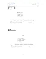
Page 16: ...for password The universal password is 1234 User can access a function by typing its corresponding number into the remote terminal To go back to the previous menu press the Backspace key Refer to the Menu Tree for navigation After enter select from one of the following functions 1 Profile 2 Configuration 3 Status Report 4 Alarm Report ...

Page 17: ...FMUX03 V35 17 Main Menu Profile ...

Page 18: ...FMUX03 V35 18 Configuration Alarm Status Report ...

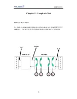
Page 19: ...FMUX03 V35 19 Status Report Data port clock source ...

Page 20: ...FMUX03 V35 20 Data port clock invert Loopback ...

Page 21: ...FMUX03 V35 21 Data rate N 64K N 1 32 N 01 08 64K 512K ...

Page 22: ...FMUX03 V35 22 N 09 16 576K 1024K N 17 24 1088K 1536K ...

Page 23: ...FMUX03 V35 23 N 25 32 1600K 2048K ...

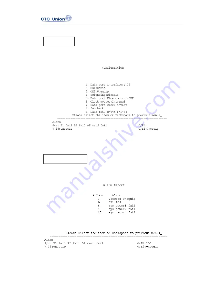
Page 24: ...st 5 1 General Information This chapter contains detailed information on the loopback tests of the FMUX03 V35 equipment User can activate the loopback function to diagnose the full service Remote side Local side V 35 Optical V 35 1 2 4 3 ...

Page 25: ...a port local loopback and remote loopback Under the Loopback selection menu user can select the channels to perform the loopback test Please refer to the diagram on the previous page for an explanation of the different loopback tests Path 1 Optical Remote Loopback Path 2 Optical Local Loopback Path 3 V 35 data port Local Loopback Path 4 V 35 data port Remote Loopback ...

Page 26: ...ta Carrier Detect DCE X 9 Receive Clock Return DCE 10 Unassigned W 11 External Clock Return DTE AA 12 Transmit Clock Return DCE 13 Unassigned S 14 Transmit Data Return DTE Y 15 Transmit Clock DCE T 16 Receive Data Return DCE V 17 Receive Clock DCE L 18 Local Loop back DTE 19 Unassigned H 20 Data Terminal Ready DTE N 21 Remote Loop back DTE 22 Unassigned 23 Unassigned U 24 External Clock DTE NN 25 ...

Page 27: ...7 CTC Union Technologies Co Ltd Far Eastern Vienna Technology Center Neihu Technology Park 8F No 60 Zhouzi Street Neihu Taipei Taiwan Phone 886 2 2659 1021 Fax 886 2 2799 1355 E mail info ctcu com http www ctcu com ...

Reviews: