FMUX03/V35
2
Table of Content
Chapter 1 Introduction………………………………….……………………
3
1-1 Functional Description………………..………………………
3
1-2 Application of FMUX03/V35…………………………………
4
1-3 Technical Specification …………………..….……………… 4
1-4 FMUX03/V35 Ordering information ..………………………..
7
Chapter 2 Installation ………………………………………………………… 8
2-1
Description…………………………………………….………
8
2-2
Unpacking………………………………………….…………
8
2-3 Site Requirements………………………..……………………
8
2-4 Site Selection……………….…………………………………. 9
2-5 AAC or DC Electrical Outlet Connection…………………….. 9
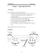
Chapter 3 Operating Instructions.……………………………………………. 10
3-1 Front Panel……………….……………………………………. 10
3-2 Rear Panel Control and LED Indicator Function..……….…..
11
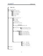
3-3
Menu
Tree……………………………………………………..
13
Chapter 4 Operating and Setup Instructions…………………………………. 14
4-1
Profile………………………………………………………….
14
4-2
System
Configuration…………….……………………………
15
4-3 Alarm Status Report………………..…………………………. 15
4-4 Craft Port Operation…………………………………………... 15
4-5 How to Connect and setup the craft port …………………….. 15
4-6 Operating From The Craft Port ……………………………….
16
Chapter 5 Loopback Test…………………………………………………….. 24
5-1
General
Information………………………………………..…
24
5-2 Loopback Test (For V.35 Tributary)………………………….. 25
Appendix-A DB25 male connector To M34 female connector
26
Summary of Contents for FMUX03/V35
Page 1: ......
Page 17: ...FMUX03 V35 17 Main Menu Profile ...
Page 18: ...FMUX03 V35 18 Configuration Alarm Status Report ...
Page 19: ...FMUX03 V35 19 Status Report Data port clock source ...
Page 20: ...FMUX03 V35 20 Data port clock invert Loopback ...
Page 21: ...FMUX03 V35 21 Data rate N 64K N 1 32 N 01 08 64K 512K ...
Page 22: ...FMUX03 V35 22 N 09 16 576K 1024K N 17 24 1088K 1536K ...


