FMUX03/V35
8
Chapter 2 - Installation
2-1 Description
This chapter provides the information needed to install FMUX03/V35. It is
important to follow the installation instruction to insure normal operation of the
system and to prevent damage due to human error.
2-2 Unpacking
If there is a possibility for future relocation of the FMUX03/V35 unit, please save the
cartons and protection packaging material. The following items are shipped with
your FMUX03/V35:
One FMUX03/V35 User’s Manual
One FMUX03/V35 Unit
V.35 Cable (DB25 to M34)
Please carefully unpack and inspect the unit and accessories for damaged and missing
parts. Contact our nearest sales representative or our company directly if you suspect
any damaged or missing parts. Improper handling during shipment may cause early
failure.
2-3 Site Requirements
The FCC requires telecommunication equipment to withstand electrical surge that
may result from lighting strikes. This equipment has been tested and found to
comply with the FCC requirement. Users should follow the precaution below to
insure the safety and minimize the risk of damage to the equipment:
Make sure that the power outlet is properly grounded. Please refer to article 250
of the National Electrical Code (NEC) Handbook.
Proper grounding should include a minimum of:
1) A grounded rod buried outside the building at least 8 feet (2.44 meters) deep.
2) It is preferred that the building uses metal water pipe and cooper connector at
the joint.
Summary of Contents for FMUX03/V35
Page 1: ......
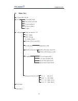
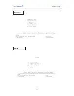
Page 17: ...FMUX03 V35 17 Main Menu Profile ...
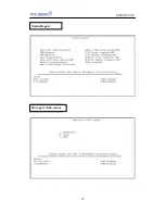
Page 18: ...FMUX03 V35 18 Configuration Alarm Status Report ...
Page 19: ...FMUX03 V35 19 Status Report Data port clock source ...
Page 20: ...FMUX03 V35 20 Data port clock invert Loopback ...
Page 21: ...FMUX03 V35 21 Data rate N 64K N 1 32 N 01 08 64K 512K ...
Page 22: ...FMUX03 V35 22 N 09 16 576K 1024K N 17 24 1088K 1536K ...


