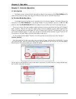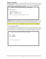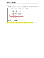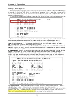
Chapter 2. Installation
20
2.5.3
SNMP
Feature
Removal
/
Replacement
***CAUTION***
This
procedure
should
only
be
performed
by
qualified
service
personnel.
In
addition,
all
power
connections
must
be
removed
before
attempting
to
open
the
case.
1.
If
the
unit
is
installed
in
a
rack,
it
must
be
removed.
2.
Follow
the
procedure
in
2.5.2
to
remove
the
top
cover.
3.
The
connector
for
the
SNMP
daughter
card
is
located
on
the
left
side
of
the
device,
when
looking
from
the
front.
The
SNMP
kit
will
include
three
stand
‐
offs,
the
SNMP
card
and
three
screws.
Insert
the
three
stand
‐
offs
and
tighten
carefully
as
they
are
brass
and
only
3.5mm.
Carefully
align
the
pins
of
the
SNMP
card,
seat
the
card,
ensuring
no
pins
are
bent.
The
three
holes
in
the
PCB
should
line
up
with
the
three
stand
‐
offs
on
the
mainboard.
4.
Install
the
three
pan
‐
head
screws
supplied.
Tighten
firmly,
but
do
not
over
tighten.
Refer
to
the
photo
below.
5.
Re
‐
install
the
top
cover.
Figure
2
‐
8
:
SNMP
module
card
Removal
/
Replacement
Summary of Contents for FMUX160
Page 2: ......
Page 34: ...Chapter 3 Operation 34 This page was left blank intentionally ...
Page 54: ......
Page 55: ......
Page 56: ......


