Chapter 3. Operation
24
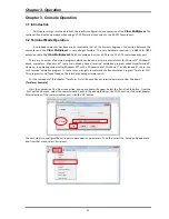
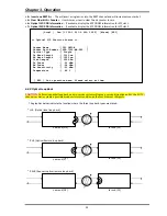
The
following
explains
the
functions
of
each
menu
item.
These
will
all
be
detailed
later:
<
1
>
Optical
Port
01
~
02
The
sub
‐
menu
provides
settings
for
ALS,
protection
mode,
loop
back,
display
bit
error
count.
<
2
>
LAN
Port
01
~
04
Leads
to
the
sub
‐
menu
to
configure
the
4
‐
port
Ethernet
switch.
<
3
>
E1
Port
01
~
08
Leads
to
the
sub
‐
menu
to
configure
E1/T1
ports
1~8.
<
4
>
E1
Port
09
~
16
Leads
to
the
sub
‐
menu
to
configure
E1/T1
ports
9~16.
<
O
>
Order
Wire
Configuration
This
sub
‐
menu
shows
the
order
wire
status.
<
A
>
Alarm
Configuration
The
alarm
status
and
configuration
is
done
on
this
sub
‐
menu
<
D
>
Device
Configuration
Information
(uptime,
power
status)
and
configuration
(reset,
factory
default)
are
here.
<
S
>
Store
Parameters
Before
leaving
the
main
menu,
store
the
settings
in
non
‐
volatile
ram.
<
U
>
Firmware
Upgrade
with
Xmodem
In
the
event
of
any
future
upgrade,
the
firmware
can
be
loaded
here.
<
P
>
Password
Setup
Sets
up
the
console
login
password
through
this
sub
‐
menu
<
R
>
Go
to
Remote
When
fiber
links
to
a
remote
unit,
this
option
is
available.
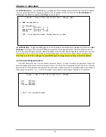
Remote
management
is
done
via
the
EOC
(Embedded
Operations
Channel)
within
the
fiber
transmission
between
a
pair
of
Fiber
Multiplexers
.
3.4.3
Device
Configuration
Menu
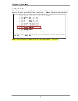
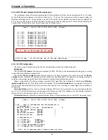
The
menu
screen
is
broken
into
two
parts,
the
informational
part
and
the
configuration
part.
Information
shown
includes
the
Uptime
of
the
device,
power
types
(AC
or
DC)
and
power
status.
<1>
Device
Active
Indicates
if
the
device
is
enabled
or
disabled.
When
disabled,
no
traffic
will
flow
through
the
device.
A
confirmation
will
be
required
to
disable
the
device.
<2>
Device
Reset
When
performing
a
device
reset
the
CPU
will
reboot,
FPGA
code
is
reloaded
and
the
saved
configuration
is
restored.
During
the
reset,
no
traffic
will
flow
through
the
device.
A
confirmation
will
be
required
prior
to
resetting.
<3>
Factory
Default
When
performing
a
factory
default,
all
configuration
settings
will
be
reverted
to
the
factory
default
settings.
Doing
a
factory
default
on
an
in
service
device
could
lead
to
traffic
disruption.
Therefore,
a
confirmation
will
be
required
before
the
factory
default
is
performed.
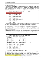
Device
Reset
and
Factory
Default
actions
could
result
in
disruption
of
traffic,
a
further
confirmation
will
be
required
by
the
user.
<4>
Clear
system
Uptime
Uptime
is
a
measure
of
the
time
the
device
has
been
working.
The
counter
can
be
zeroed
using
this
function.
[Local ] Ver:[1.100-1.003-0.000-1.000] [Alarm]
<< Device Information and Configuration >>
< Information >
Uptime [ 10 : 12 : 04 ] S/N [ C49102332600000000001 ]
Power 1 [ AC Power ] [Fixed ] [UP ]
Power 2 [ DC Power ] [Fixed ] [Down]
< Configuration >
<1> Device Active [Enable ] <4> Clear system Uptime
<2> Device Reset <5> SNMP Information
<3> Factory Default <6> SNMP [Enable ]
[ ESC ] Go to previous menu. Please select an item.
------------------------------------------------------------------------------
< Confirmation >
WARNING!! Resetting device will momentarily block all traffic.
Are you sure?
<Y> Yes <Esc> Exit
Summary of Contents for FMUX160
Page 2: ......
Page 34: ...Chapter 3 Operation 34 This page was left blank intentionally ...
Page 54: ......
Page 55: ......
Page 56: ......


