Chapter 3. Operation
28
3.4.8
Aggregate
Configuration
When
we
use
the
term
aggregate,
we
are
referring
to
the
optical
section
of
the
multiplexer.
All
of
the
tributary
channels
(E1/T1,
LAN,
Order
Wire,
RS
‐
232)
are
multiplexed
or
"aggregated"
into
the
optical
fiber
transmission.
The
received
optical
transmission,
which
contains
all
of
the
multiplexed
signals,
is
de
‐
multiplexed
back
into
the
appropriate
tributary
channels.
To
enter
the
configuration
menus
for
the
aggregate,
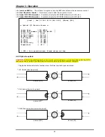
select
the
"Optical
Port"
menu
item
from
the
main
menu
page.
The
menu
screen
is
broken
into
two
parts,
the
informational
part
and
the
configuration
part.
The
two
optical
ports
work
to
provide
redundancy
in
the
event
of
any
hardware
failure
or
fiber
cable
breakage
or
disconnection.
Type
:
Will
be
listed
as
either
"1
*
9"
which
is
a
fixed
transceiver,
or
as
"
SFP
"a
small
form
pluggable
transceiver.
Link
:
This
indicates
the
state
of
the
optical
link,
either
UP
or
DOWN.
DDM
:
Digital
Diagnostic
Monitor
is
an
optional
feature
of
SFP
modules.
An
SFP
which
supports
DDM
offers
additional
diagnostic
information
such
as
Tx
Power,
Rx
Power
and
internal
temperature.
The
fiber
multiplexer
is
able
to
read
and
monitor
this
information
if
available.
Working
Path
Status
:
When
1+1
optical
protection
is
utilized,
one
of
the
optical
paths
is
active
or
"working"
while
the
other
path
is
standing
by.
The
status
here
shows
which
optical
interface
is
providing
the
working
or
active
path.
bit
Error
Counter
:
The
multiplexer
maintains
a
constantly
running
bit
error
rate
channel
as
one
of
the
multiplexed
streams.
If
the
optical
path
has
transmission
errors,
this
stream
will
show
an
increasing
bit
error
count.
The
counter
register
can
be
cleared
and
then
monitored
over
an
extended
time,
looking
for
any
optical
transmission
errors.
<
1
>
Protection
Mode
:
Choose
the
mode
of
optical
protection,
non
‐
revert,
revert
or
manual
(non
‐
revert
default).
<
2
>
ALS
:
Enable
or
Disable
the
Auto
Laser
Shutdown
safety
feature
here
(disabled
by
default).
<
3
>
Loopback
Test
:
Take
care
when
doing
fiber
loopback
test
as
ALL
the
aggregate
channel
will
be
looped,
including
the
Ethernet.
If
an
Ethernet
port
is
connected
to
an
active
network,
the
multiplexer
will
create
a
broadcast
storm.
Please
exercise
care
when
performing
optical
loopback.
(See
next
page
for
loopback
details.)
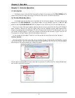
[Local ] Ver:[1.100-1.003-0.000-1.000] [RDI]
< 1 > Optical Port 01 ~ 02
< 2 > LAN Port 01 ~ 04
< 3 > E1 Channel 01 ~ 08
< 4 > E1 Channel 09 ~ 16
< O > Order Wire Configuration
< A > Alarm Configuration
< D > Device Configuration
< S > Store Parameters
< U > Firmware Upgrade with Xmodem
< P > Password Setup
< R > Go to Remote
[ ESC ] Logout
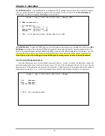
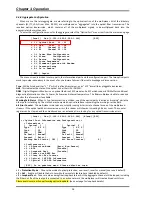
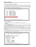
[Local ] Ver:[1.100-1.003-0.000-1.000] [Alarm] [RDI]
<< Optical Port Information and Configuration >>
< Information >
[ Optical 1 ] [ Optical 2 ]
Type [ S F P ] Type [ S F P ]
Link [ UP ] Link [ UP ]
DDM [ DDM ] DDM [ None ]
Tx Fault [ Normal] Tx Fault [ Normal]
Present [ Exist ] Present [ Exist ]
Working Path Status [ OP1 ] bit Error Counter [ 0]
< Configuration >
< 1 > Protection Mode [Auto, Non-Revert]
< 2 > ALS [Disable]
< 3 > Loopback Test [Disable]
< 4 > Insert one BERT Err
< 5 > Clear bit Err Counter
< 6 > Optical 1 SFP-DD Information
< 7 > Optical 2 SFP-DD Information
[ ESC ] Go to previous menu. Please select an item.
Summary of Contents for FMUX160
Page 2: ......
Page 34: ...Chapter 3 Operation 34 This page was left blank intentionally ...
Page 54: ......
Page 55: ......
Page 56: ......


