Chapter 3. Operation
33
The
second
L2
switch
option
is
the
Port
Based
VLAN
configuration.
The
Virtual
LANs
are
created
by
assigning
the
LAN
channels
to
one
of
4
(four)
VLAN
groups,
A,
B,
C,
or
D.
When
each
channel
is
assigned
a
different
group
the
4
(four)
LAN
channels
will
have
their
traffic
isolated
from
the
other
channels
so
that
traffic
on
local
FMUX
channel
1
will
only
appear
on
the
remote
FMUX
channel
1.
Channel
2
will
only
appear
on
the
remote
channel
2,
and
so
on.
The
Port
Based
VLAN
setting
is
selected
by
using
the
"V"
menu
item.
The
below
screen
is
an
example
of
isolating
each
channels
traffic
using
the
Port
Based
VLAN.
The
settings
need
to
be
duplicated
on
both
multiplexers.
Do
not
forget
to
save
the
settings
under
the
"Device"
menu.
This
completes
the
console
based
setting
part
of
configuration
for
the
fiber
multiplexers.
If
an
optional
SNMP
module
has
been
installed
in
at
least
one
of
the
multiplexer
pair,
then
both
SNMP
and
an
easy
to
use
Web
based
manager
are
available
to
the
engineer
for
local
and
remote
configuration
and
monitoring.
The
TCP/IP
configuration
and
use
of
the
Web
based
management
are
covered
in
the
next
chapter.
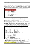
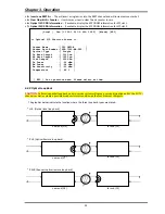
[Local ] Ver:[1.100-1.000-0.000-0.050] [Alarm] [RDI]
<< Port VLAN Information and Configuration >>
< 0 > Port VLAN [Disable]
Group A Group B Group C Group D
< 1 > Port 01 [*] [ ] [ ] [ ]
< 2 > Port 02 [ ] [*] [ ] [ ]
< 3 > Port 03 [ ] [ ] [*] [ ]
< 4 > Port 04 [ ] [ ] [ ] [*]
[ ESC ] Go to previous menu. Please select an item.
Summary of Contents for FMUX160
Page 2: ......
Page 34: ...Chapter 3 Operation 34 This page was left blank intentionally ...
Page 54: ......
Page 55: ......
Page 56: ......


