Chapter 1 Introduction
8
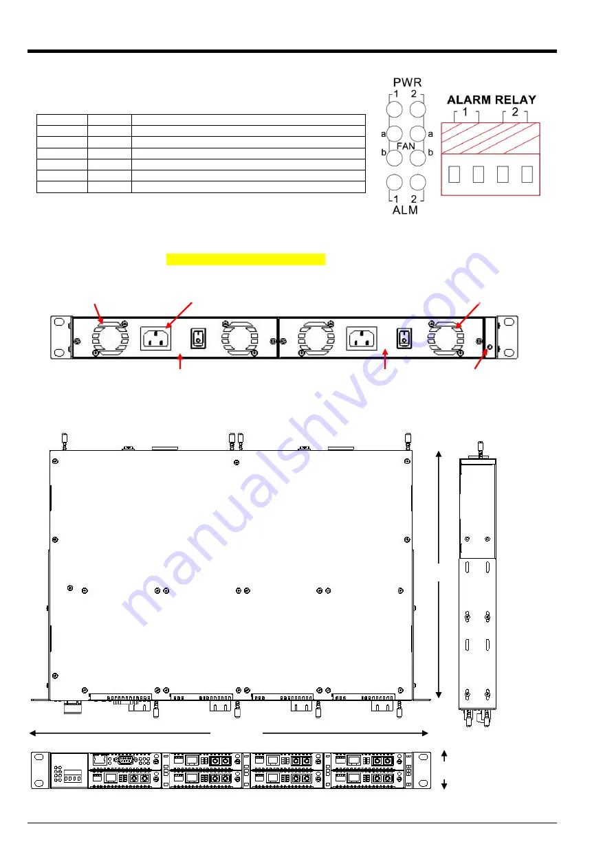
1.3 LED Indicators and Alarm Relay
LED
Color
Indication
PWR 1
Green
When On, indicates good power from module #1
PWR 2
Green
When On, indicates good power from module #2
FAN a
Green
When On, left fan of power module is OK
FAN b
Green
When On, right fan of power module is OK
ALM 1
Red
When On, NMC has set Alarm 1 ON, relay 1 is closed
ALM 2
Red
When On, NMC has set Alarm 2 ON, relay 2 is closed
Figure 1-2 Relays and LEDs
1.4 Chassis Rear Description
The rear panel holds the hot-swappable power/fan modules. The pluggable modules do not require any tools
for removal or replacement.
Figure 1-3 Chassis Rear View
1.5 Chassis Physical Dimensions
Figure 1-4 Chassis Dimensions, in millimeters
Cooling Fan (a)
IEC AC Mains Input
Power Module 1
AC Type Shown
Power Module 2
AC Type Shown
Cooling Fan (b)
Protective Earth (PE)
Terminal
482.6mm
44mm
302mm
Summary of Contents for FRM220-CH08
Page 1: ...FRM220 CH08 Hardware Installation...
Page 2: ......
Page 6: ...Table of Contents ii...
Page 18: ...Chapter 3 Management Quick Start 18...
Page 19: ......
Page 20: ......


