


FRM220 Chassis Quick Installation Guide
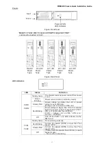
24
Installation
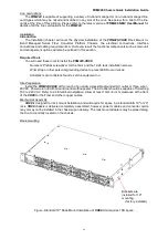
The Installation will cover the physical installation of the
FRM220-CH04A
, Rack Mount In-Band
Managed Series Fiber Converter Platform Chassis, the electrical connections, interface connections
and cabling requirements. A brief overview of the functional components such as main unit and
management options will also be outlined in this section.
Required Tools:
You will need these tools to install the FRM220-CH04A:
Number 2 Phillips screwdriver for the 3mm and the 12-24 rack installation screws.
Wrist strap or other personal grounding device to prevent ESD occurrences.
Antistatic mat or antistatic foam to set the equipment on.
Site Preparation
Install the
FRM220-CH04A
within reach of an easily accessible grounded AC outlet or three wire (-
48VDC, Power return, Earth Ground) central office power. The AC outlet should be capable of furnishing
100 to 240 VAC. Refer to 2.4 Electrical Installation. Allow at least 10cm (4 inch) clearance at the front
of the
CH04A
for the Fiber and other copper cables.
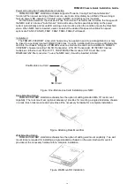
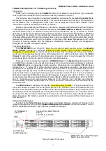
Mechanical Assembly
CH04A
is designed for rack mount installation and will require 1U space in a standard EIA 19" or
23" rack.
CH04A
chassis is delivered completely assembled, however power modules and converter
cards may or may not be installed in the chassis upon delivery. The rack mount adapters may be placed
along the front or centrally located on the chassis.
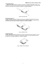
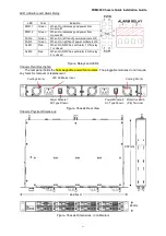
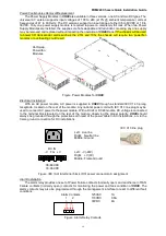
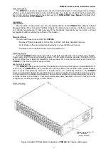
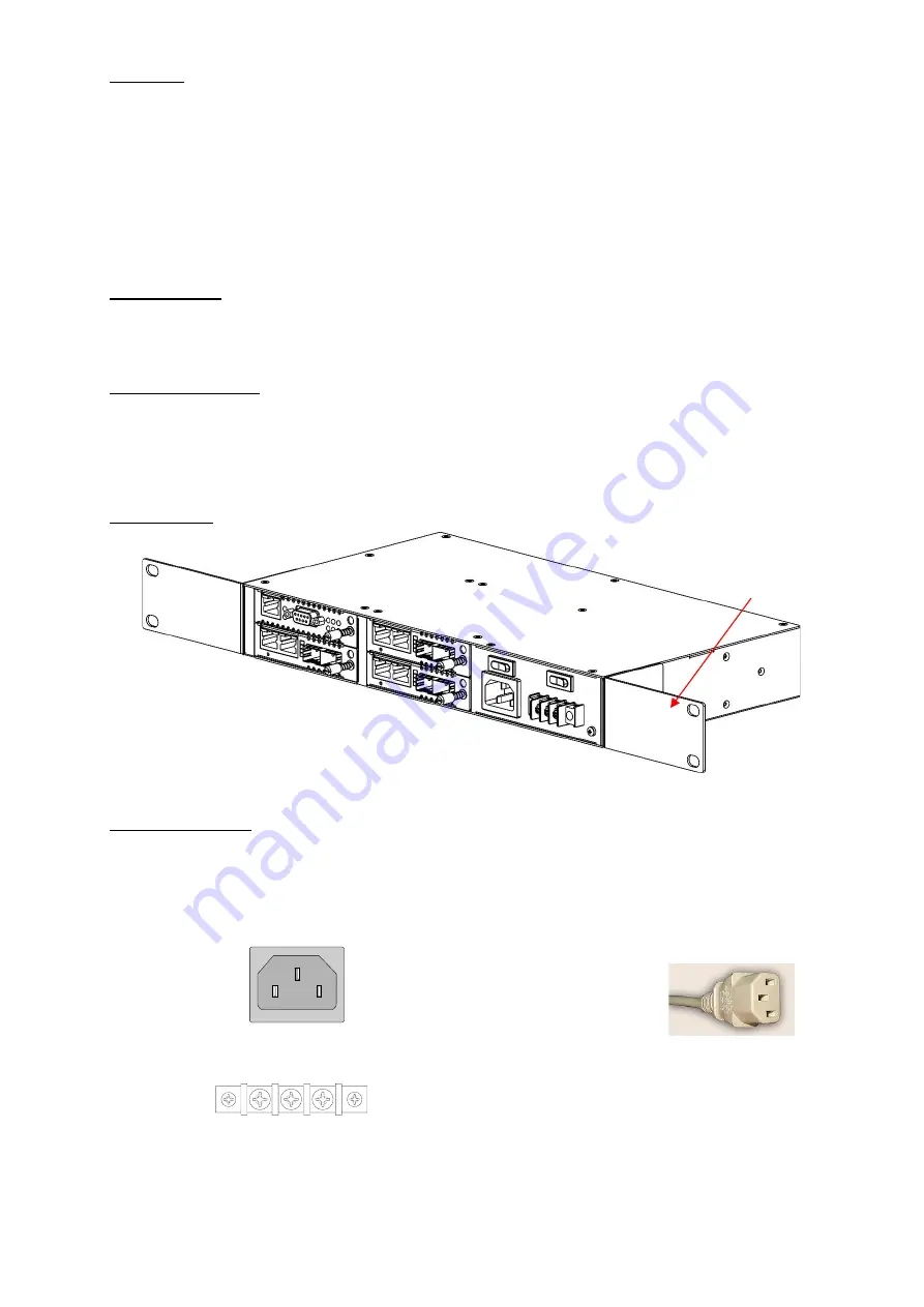
Rack mounting
Figure. Standard 19" Rack-Mount Installation of
CH0A4
Unit requires 1RU space
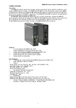
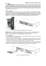
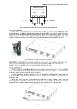
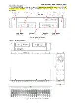
Electrical Installation
With an AC power module, AC power is supplied to CH04A through a standard IEC C14 3-prong
receptacle, located on the right hand side of the front panel module. Any national power cord with IEC
C13 line plug may be used to connect AC power to the power module. With a DC24 or DC48 module,
DC voltage is connected to the terminal block located on the rear of the module, observing the proper
polarity. CH04A should always be grounded through the protective earth lead of the power cable in AC
installations, or via the frame ground connection for DC installations.
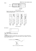
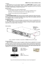
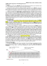
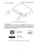
Figure. IEC (AC) & terminal block (DC) power connector pin assignment
Brackets are
installed for 19"
mounting.
(factory installed)
Left: Live line
Right: Neutral line
Middle: Ground
Left: -V
Right: +V
Middle: Frame Ground
DC IN
-V FG +V
18~60VDC


