
FRM220 Chassis Quick Installation Guide
38
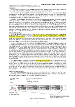
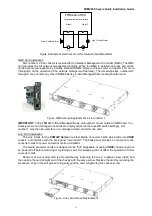
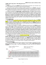
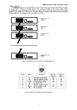
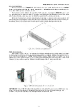
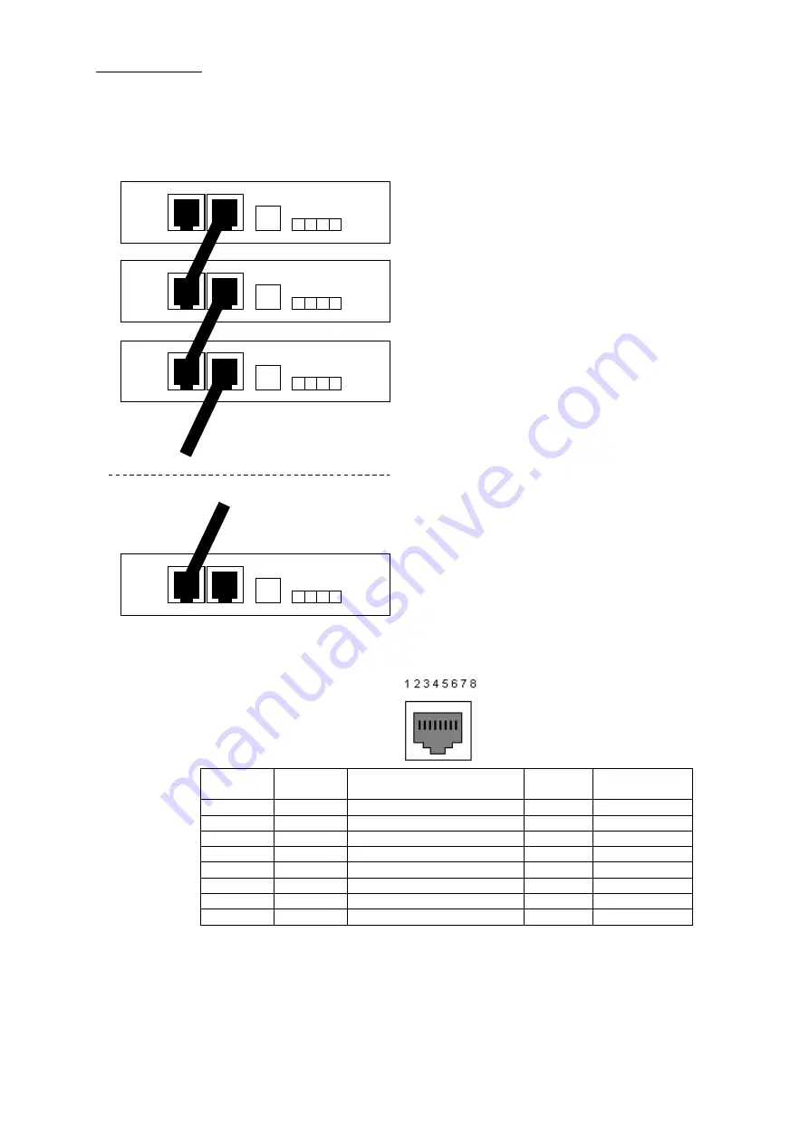
Chassis Cascade
The
FRM220
chassis may be cascaded in such a manner that only one single IP address is required
to manage up to 10 chassis in a single location. The connection diagram is shown below. Each chassis
is assigned a unique ID starting at zero for the master chassis and incrementing for each cascaded
chassis, up to an ID of nine. The "out" of the parent chassis connects to the "in" of the slave using any
standard Ethernet UTP straight cable with RJ-45 connectors.
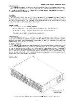
Figure. Cascade Ports Connections and ID assignment
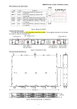
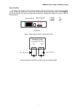
Pin No.
Signal
Definition
Direction
(Master)
Direction
(Slave)
1
Tx+
Transmit positive signal
Out
In
2
Tx-
Transmit negative signal
Out
In
3
Rx+
Receive positive signal
In
Out
4
Chain+
Chain positive signal
Out
In
5
NC
No connection
6
Rx-
Receive negative signal
In
Out
7
Chain-
Chain negative signal
Out
In
8
NC
No connection
Figure. Cascade Ports Detailed Pin Assignment
IN OUT
IN OUT
IN OUT
IN OUT
Chassis ID = 0
(Master)
Chassis ID = 1
(Slave)
Chassis ID = 2
(Slave)
Chassis ID = 9
(Slave)
9
2
0
1


