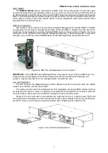
FRM220 Chassis Quick Installation Guide
22
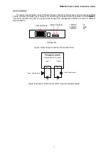
FRM220 Series In-Band Managed
Media Converter Cards
NMC
10/100Base-TX
Ethernet
Console Port (DB9F RS-232 Async)
115,200, 8, N, 1-DCE
FRM220-CH04A Four Slot Stand-alone Chassis
Introduction
Thank you for choosing the
FRM220-CH04A 4-Slot Chassis
.
This manual is used to explain the hardware installation procedures for the 4-slot Converter Rack
and present its capabilities and specifications. This manual is divided into 2 Sections, the Introduction
and the Installation.
Installers should carefully read Installation.
Description
The FRM220-CH04A is a 1U high (19" Rackmount option), 4 slot modular media converter center.
The Modular Media Chassis provides an economic solution for high density Fiber Converter installations
in enterprises or central offices. All interface cards are hot swappable allowing online field replacement.
An additional feature allows the Media Chassis to detect the working or failing status either of power
module or any fan assembly in the unit and activate relays that can be used to control external alarm
devices.
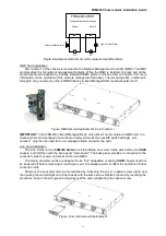
There are 4 slots available for installation of FRM220 Cards in the Media Chassis compact rack. An
SNMP Card is installed in the far left hand, upper slot, for local and remote management purposes.
Each FRM220 Card is an independent media converter. When linked to a compatible FRM220 Series
stand-alone or "I" series FMC (Fiber Media Converter) stand-alone converter, complete in-band
management is supported. All settings of the line card and remote connected stand-alone device may
be managed through any of the available management interfaces. A variety of cards are available that
support multi-mode or single-mode fiber types and connections to SC, ST, FC or even the latest bi-
directional single fiber WDM (Wave Division Multiplexing) in ranges from 2Km to 120Km. Converter
cards include Fast Ethernet, Gigabit Ethernet, Serial (RS-485, RS-232 and RS-422), ITU-T G.703 E1
and T1, Synchronous and Asynchronous Datacom (V.35, RS-530, X.21, RS-449, and RS-232),
155.52M STM-1 repeater, transponders for 2.7G, 4G and 10G, FXO/FXS over fiber and more as the
product matures.
The Media Chassis optionally incorporates fixed redundant power modules. The supply, depending
on the model, derives its power from an AC power source (100~240VAC) and/or DC power source
(18~72VDC). When two modules are installed, they provide for power redundancy during the Line Cards'
transmissions. The Line Cards provide all copper and fiber interface connections on the face of each
Line Card, along with status indicator LEDs. The status LED indicators provide for quick indications of
both copper and fiber link statuses and fault detection.
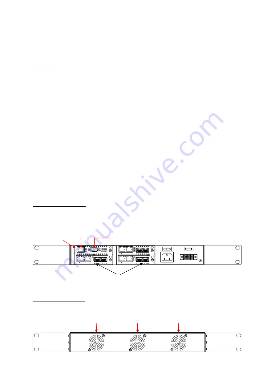
Chassis Front Description
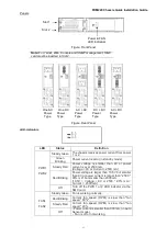
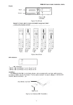
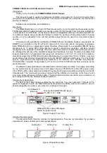
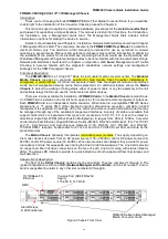
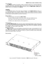
The front of the 4-Slot Chassis contains the line card slots. They are numbered 1 through 4. The
typical configuration is with one NMC (Network Management Controller) card in slot number 1 and in-
band manageable line cards in any other slot numbered 2 through 4.
Figure. Chassis Front View
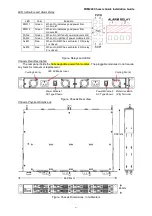
Chassis Rear Description
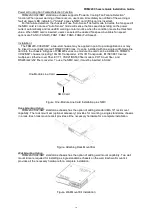
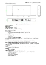
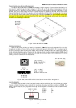
The rear panel holds three fan modules for heat dissipation. They are not removable. If you need a
replacement, please contact your sales representative.
Figure. Chassis Rear View
Cooling Fan
Cooling Fan
Cooling Fan


