Appendix B: Cable Pinout Definition Tables
24
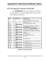
B.2 User DATA Port Connector For RS-232
The
MUX128/2*64
user data channel for RS-232
physical interface is a 25-pin female D-type connector wired
in accordance with Table B-2.
Abbr.
Pin
Direction
Description
FG
1
↔
Chassis ground.
May be isolated from signal ground.
SG
7
↔
Signal Ground.
TD
2
To
MUX128/2*64
Serial digital data from DTE.
RD
3
From
MUX128/2*64
Serial digital data at the output of the
MUX128/2*64
/2*64K receiver.
RTS
4
To
MUX128/2*64
Supply an ON signal to the
MUX128/2*64
/2*64k when data
transmission is desired.
CTS
5
From
MUX128/2*64
Constantly ON or follow RTS. (by DIP
SW setting).
DSR
6
From
MUX128/2*64
Constantly ON,
Except during test loops.
DTR
20
To
MUX128/2*64
Not used.
DCD
8
From
MUX128/2*64
Constantly ON.
ETC
24
To
MUX128/2*64
A transmitted data rate clock input
from the data source.
TC
15
From
MUX128/2*64
A transmitted data rate clock for use by
an external data source.
RC
17
From
MUX128/2*64
A received data rate clock for use by an
external data source.
Table B-2 RS-232 pin allocation
Summary of Contents for MUX128
Page 1: ...INSTALLATION and OPERATIONMANUAL ...
Page 2: ......
Page 26: ...Appendix A DIP Switch Setting Tables 22 This page left blank intentionally ...
Page 34: ......
Page 35: ......

