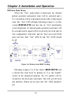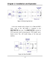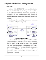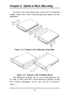
Appendix B: Cable Pinout Definition Tables
28
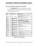
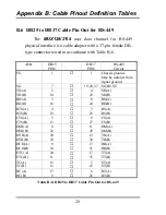
B.6 DB25 to DB37 Cable Pin Out for RS-449
The
MUX128/2*64
user data channel for RS-449
physical interface is a cable adapter with a 37-pin female DB-
type connector wired in accordance with Table B-6.
Abbr.
DB25
PIN#
DB37
PIN#
RS-449
Circuit
FG
1
↔
1
Chassis ground.
May be isolated from
signal ground.
SG
7
↔
19,20,37
SG,RC,SC
TD(A)
TD(B)
2
14
↔
↔
4
22
SD(A)
SD(B)
RD(A)
RD(B)
3
16
↔
↔
6
24
RD(A)
RD(B)
RTS(A)
RTS(B)
4
19
↔
↔
7
25
RS(A)
RS(B)
CTS(A)
CTS(B)
5
13
↔
↔
9
27
CS(A)
CS(B)
DSR(A)
DSR(B)
6
22
↔
↔
11
29
DM(A)
DM(B)
DTR(A)
DTR(B)
20
23
↔
↔
12
30
TR(A)
TR(B)
DCD(A)
DCD(B)
8
10
↔
↔
13
31
RR(A)
RR(B)
ETC(A)
ETC(B)
24
11
↔
↔
17
35
TT(A)
TT(B)
TC(A)
TC(B)
15
12
↔
↔
5
23
ST(A)
ST(B)
RC(A)
RC(B)
17
9
↔
↔
8
26
RT(A)
RT(B)
Table B-6: DB25 to DB37 Cable Pin Out for RS-449
Summary of Contents for MUX128
Page 1: ...INSTALLATION and OPERATIONMANUAL ...
Page 2: ......
Page 26: ...Appendix A DIP Switch Setting Tables 22 This page left blank intentionally ...
Page 34: ......
Page 35: ......

