4
•
Output selectable between acceleration, velocity, or displacement (varies
by configuration)
•
Ten available full-scale ranges from 0 .5 to 500 (g’s, IPS, mm/sec, mils; the
maximum full-scale range varies based on input sensor activity)
•
Two buffered dynamic outputs, one via BNC and one via terminal blocks
•
35 mm DIN rail mountable
•
Removable terminal blocks facilitates easy wiring
Installation
Electrical Connections
1
2
3
4
9
10
11
12
5
6
7
8
13
14
15
16
Temperature Output (+)
Temperature Output (-)
Dynamic Output (+)
Channel 1 Output (-)
Channel 1 Output (+)
CAN High
CAN Low
Dynamic Output (-)
Power In (+)
Power In (-)
Temperature Input (+) (.1 to 1.7 V)
Sensor Drain Wire (GND)
Vibration/
Temperature Common (-)
Vibration Signal In (+)
4-20 mA
Output
Dynamic
Signal Output
+20 - 32VDC
Common
0-5 VDC, 0-10 VDC,
4-20 mA, 0-20 mA
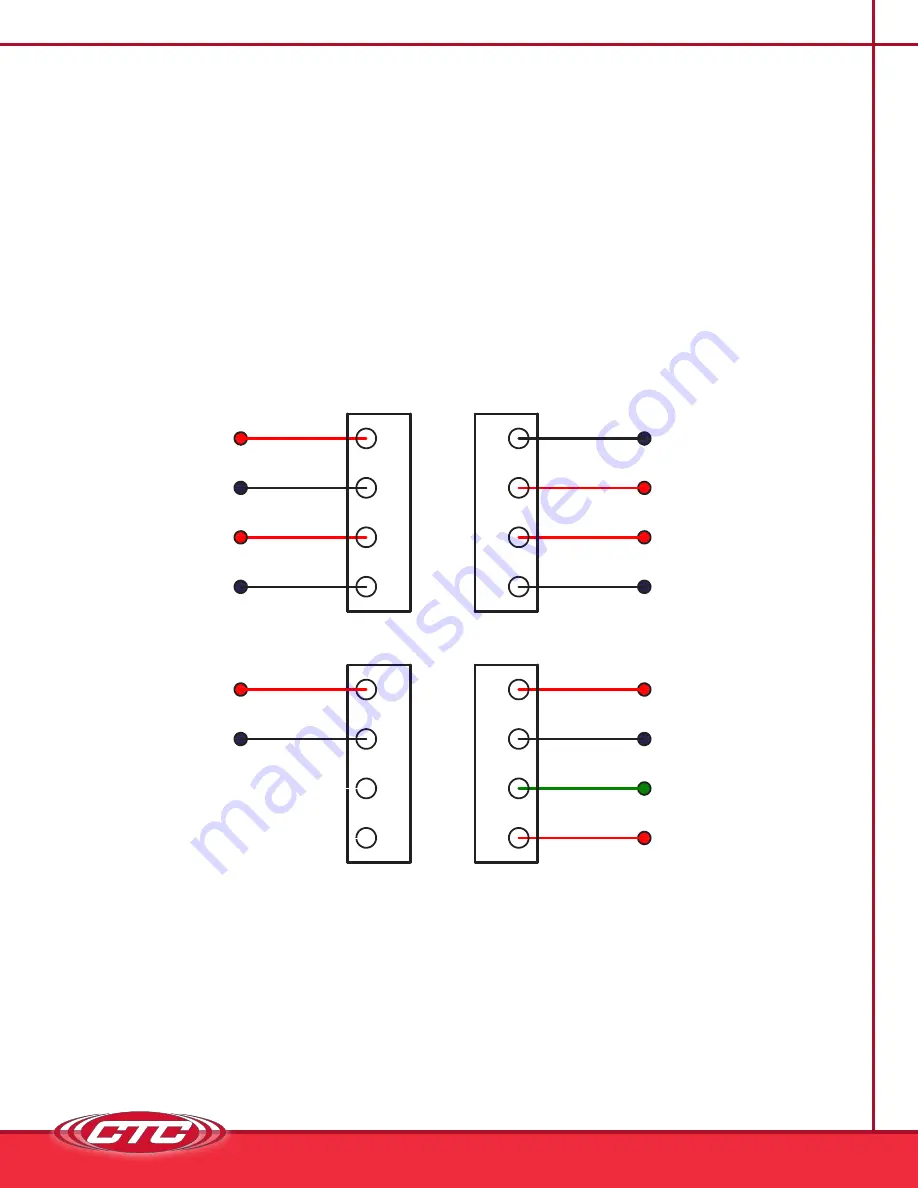
SIGNAL CONDITIONER ELECTRICAL WIRING DIAGRAM
FOR SINGLE CHANNEL IEPE ACCELEROMETER INPUT
Figure 1. Signal Conditioner Electrical Wiring Diagram
for Single Channel IEPE Accelerometer Input, with Temperature


