5
1 .
Connect the +20 - 32
V
dc
power lead to the terminal marked 5 and the negative
or common to the terminal marked 6 .
2 .
For single channel accelerometer input connection, wire the sensor leads to
13(+), 14(-), and 15(shield drain wire) as shown in Figure 1 . If using a TA series
sensor, the temperature out lead is attached to terminal 16 .
3 .
Connect the output device to terminals 11(+) and 12(-) for channel one’s
4-20 mA signal proportional to the vibration level .
4 .
Connect output device to terminals 1(+) and 2(-) to obtain the 4-20 mA signal
representative of temperature level .
5 .
Terminals 7(+) and 8(-) are inactive for single channel signal conditioner builds .
6 .
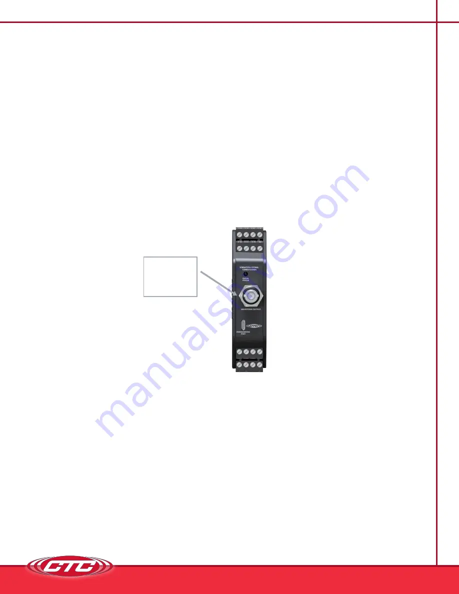
The dynamic signal output can be obtained from the BNC connector at the top
of the signal conditioner or from terminals 3(+) and 4(+) .
Terminal connections are also listed on the side of the signal conditioner .
Figure 2. Signal Conditioner — Dynamic Signal Output BNC
DYNAMIC
SIGNAL
OUTPUT


